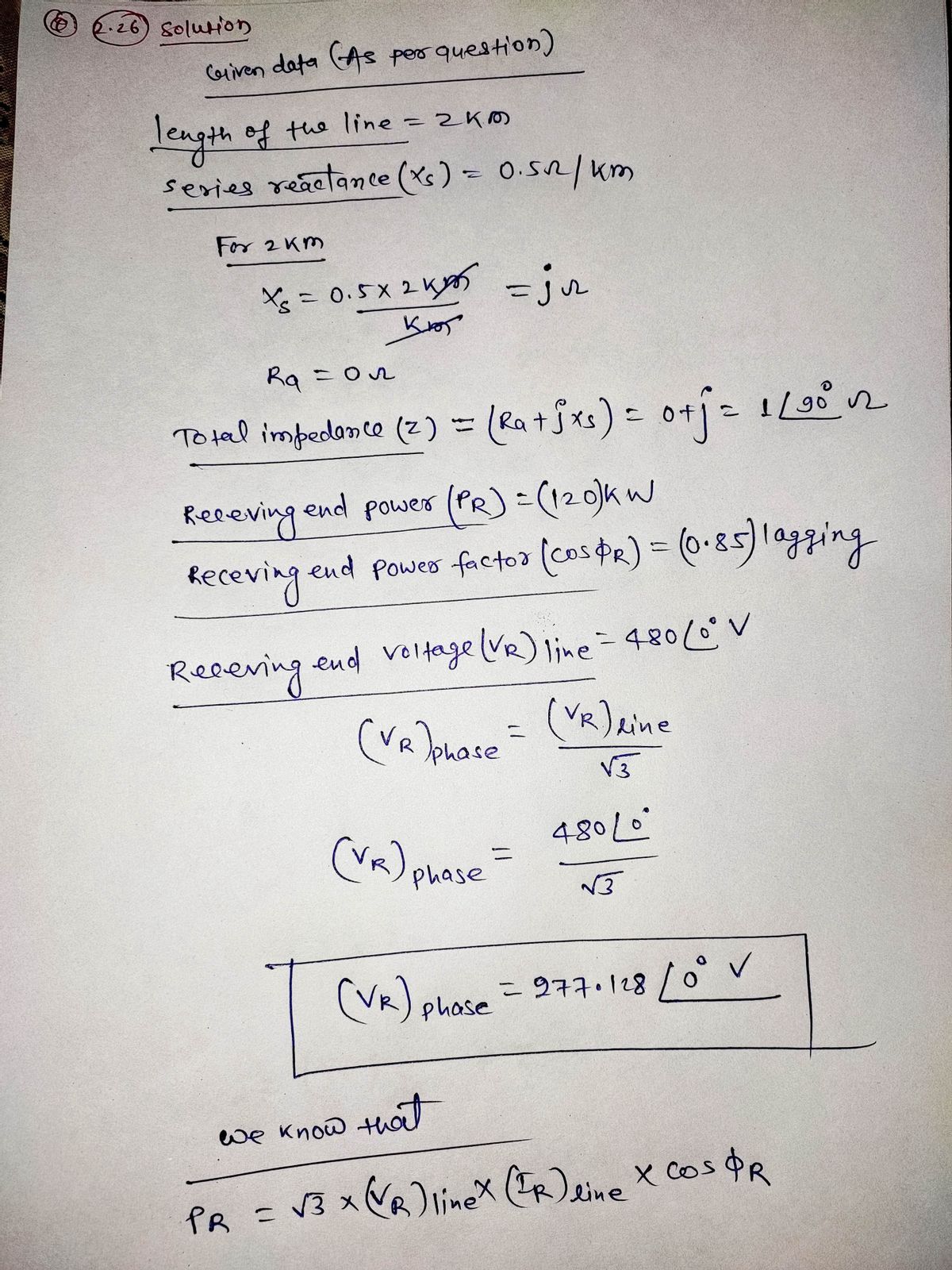
factor at the sending end oI the transmissi
Q: The signal conditioning circuit given at the left side of the operational amplifier is a 46 C₁ O low…
A:
Q: determine voltaeg gain
A: Given circuit is consist of an operational amplifier the voltage gain of the given operational…
Q: A basic switching regulator is shown in Figure 17-49. If the switching frequency of the transis- tor…
A: For the given circuit the value of the output voltage of the basic switching regulator needs to be…
Q: 3x8 multiplexer Ca,b,c are mux inputs): a フ+
A: The function at each output terminal of a decoder is a min term and the function is given is max…
Q: If the maximum analog frequency is 50Hz, the minimum sampling frequency to avoid aliasing is 75Hz…
A:
Q: Problem D continued b. Determine Vout for the given input signal
A: Need to analyze the circuit to find the output waveform. The given circuit is an inverting Schmitt…
Q: 1. (Swap) CLR' with PRE' position with same pulse widths. 2. Redraw the timing waveforms: 3. Does…
A: 1. Swapping CLR' with PRE' position with same pulse widths:Swapping the positions of CLR' and PRE'…
Q: Determine the transition state voltage, Vi and Vo using ON and OFF assumption. Draw the transfer…
A:
Q: When you add delay(1000), what is the duration of the delay component? Check all that apply O 1000…
A: We will try to check the options one by one and thereby choose the correct answers possible as shown…
Q: A differentiator has a gain of 15 dB at 0.5 kHz and a 1.5 Vpp 0.5 kHz triangle wave as its input.…
A: GivenThe gain of the differentiator is 15db and Vin =1.5VWhat is expected output
Q: In a receiver the input signal is 100 V, while the internal noise at the input is 10 V. With…
A:
Step by step
Solved in 5 steps with 5 images
- The VSWR on an 50-Ohm transmission line is 5. The distance between successive voltageminima is 80 cm while the distance from the load to the first minimum is 30 cm. What are thereflection coefficient and load impedanceA three-phase, 60-Hz, untransposed transmission line runs in parallel with a telephone line for 20 km. The power line carries a balanced three-phase rms current of Ia = 3202 – 240°A. The line configuration is as shown in figure. Assume zero current flows in the ungrounded telephone wires. Find the magnitude of the voltage induced in the telephone line. = 32020°A, Ī, = 3204–120°A, and a 4 m 4 m 5 m d G2 mOA surge of 100 kV travels along an overhead line towards its junction with a cable. The surge impedance for the overhead line and cable are 400 ohms and 50 ohms respectively. The magnitude of the surge transmitted through the cable is ?
- Develop a small-scale equivalent transmission line pi model (per phase) of the transmission lines with the specification given in table 1. The conductors are placed with a flat horizontal spacing of 7.25 meters. Consider that the load connected against the line 125MW at 0.85 lagging power factor. You are required to develop an equivalent model for a maximum 220V (RMS) sending and receiving end voltage and a maximum of 5A load current. Sr. NTDC Transmission Line Length Conductor No. Туре 220 kV DG Khan-Loralai Transmission Line (227 km) 227km Pheasant TABLE AJ Electrical characteristics of bare aluminum conductors steel-relnforced (ACSR)+ Reniertance Reactance per conductor 1-ft apacing. 60 Ha Ae, 60 Ha Capaitive Aluminum ares, emil Layers of Outaide aluminum diameter, in a/1,000 ft soC, D/ml GMR Induetive Stranding AL/8t De, 20°C. 20C, a/mi Code word D. t Ma-mi Waswing Partridge Ostrieh Merlin Linnet Oriole Chickndee Ibin Pelienn Flicker Hawk 266,800 206,800 300,000 336, 400 336.400…The load flow data for the sample power system are given below. The voltage magnitude at bus 2 is to be maintained at 1.04 p.u.Determine the set of load flow equations at the end of first iteration by using N-R method. Impedance for sample system Bus Code Impedances line charging admittance 1-2 0.08 + j0.24 0.0 1-3 0.02 + j0.06 0.0 2-3 0.06 + j0.18 0.0 Schedule of generation and loads: Bus Code Assured Voltages Generation Load…Quest- A single phase 50 Hz, system supplies an inductive load of 5000 kw at power factor 0.8 lag through a line 25 km. Resistance of the line is 0.0195 2/km and inductance = 0.36 mH/km, receiving end voltage is 10 kV. A capacitor is connected across the load to get the voltage regulation of 10%. Ratio of transmission line loss with and without shunt capacitor is
- A single phase 50 Hz generator supplies an inductive load of 5,000 kW at a power factor of 0.707 lagging by means of an over head transmission line 20 km long. The line resistance and inductance are 0.0195 ohm and 0.63 mH per km. The voltage at the receiving is required to be kept constant at 10 kV Q1. the sending end voltage and voltage regulation of line Q2. the value of the capacitor to be placed in parallel with the load such that the regulation is requced to 50 % of that obtained in Q1 Q3. compare the transmission efficiency in parts of Q1 & Q2.... (Time) From midnight to From 3 a.m to A generation station of 500 kw supply a two regions A & B .The line losses are neglected. And the load variation of these regions is as follow. Region A From From 10 a.m to From 5 p.m to Load (kw) Region B (Time) 3 a.m 90 From 10 a.m 30 From 5 p.m 100 From. 9 p p.m 60 From 9 p.m to midnight 120 From midnight to 6 a.m to 9 a.m to Load (kw) 6 a.m 40 9 a.m 90 4 p.m 130 / 4 p.m to 7 p.m 7 p.m to midnight 80 50 1-Plot The daily load duration curve of the total system. 2-Find the load factor, diversity factor,plant user factor and maximum actual generation by the station in kwh in the day for the total system.A 60-Hz, single-phase power line and a telephone line are parallel to each other as shown in the following figure. The telephone line is symmetrically positioned directly below phase b. The power line carries an rms current of 226 A. Assume zero current flows in the ungrounded telephone wires. Find the magnitude of the voltage per Km induced in the telephone line. 5 m 3 m d 2*mO
- The figure shows a 500-kV (line-to-line voltage) transmission line linking two systems. The theoretical maximum power that can be transferred from System A to System B is 5,000 MW, which occurs when the power angle 8 = 90°. The line current is then proportional to (VA - VB) The reactive power losses (Mvar) in the transmission line during this transfer would be most nearly: Wond O A. 1,667 O B.. 3,333 O C. 5,000 O D. 10,000 Know EQUIVALENT SYSTEM A VA= 500 28 KV m XL = 50 Ω EQUIVALENT SYSTEM B VB = 500 40⁰ kV Oelectrical engineering department plzz solve220 kV, 50 Hz, 200 km line has its conductors on the corners of a triangle with sides 6 m. 6 m and 12 m. The conductor radius is 1.81 cm. Find the capacitance per phase per km. [B.T.E. Pb. Elec. Power I December 1995) (Ans. 1.844 F) Into the