Every wire carries a single value. Please help me write the "truth" table (in canonical form - with the inputs "counting up") for this circuit.
Every wire carries a single value. Please help me write the "truth" table (in canonical form - with the inputs "counting up") for this circuit.

Introductory Circuit Analysis (13th Edition)
13th Edition
ISBN:9780133923605
Author:Robert L. Boylestad
Publisher:Robert L. Boylestad
Chapter1: Introduction
Section: Chapter Questions
Problem 1P: Visit your local library (at school or home) and describe the extent to which it provides literature...

Related questions

Question
Every wire carries a single value.
Please help me write the "truth" table (in canonical form - with the inputs "counting up") for this circuit.

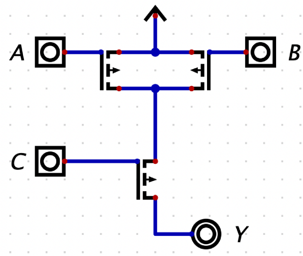
Transcribed Image Text:The image depicts a logic circuit diagram with four main components labeled A, B, C, and Y.
### Description of the Logic Circuit:
1. **Inputs:**
- **A:** Represents one input terminal located at the top left.
- **B:** Represents a second input terminal located at the top right.
- **C:** Represents a third input terminal located at the bottom left.
2. **Connections:**
- All three input terminals, A, B, and C, are connected through blue lines to a series of logic gates indicated by the black symbols with arrows.
- Two lines intersect, forming connections that manipulate the input signals before reaching the output.
3. **Logic Gates:**
- The circuit includes multiple logic gates at intersections:
- The horizontal line between A and B contains two gates facing opposite directions.
- The vertical line connecting C to the main path includes another gate facing upwards, indicating signal processing.
4. **Output:**
- **Y:** Represents the output terminal located at the bottom right.
5. **Direction:**
- The black arrow at the top of the circuit indicates the flow direction of signal processing within the circuit.
This diagram is used to illustrate how different logic gates and inputs are interconnected to produce an output signal in a digital circuit. Each section may represent various logical operations such as AND, OR, NOR, etc., essential for understanding digital electronics and logic design.
Expert Solution
Step 1: What is given and what to do:
Given:
a PMOS circuit,
we need to:
create a truth table for all three inputs counting up.
Note:
In PMOS, if the gate voltage is LOW (Gate = 0), the circuit behaves as ON switch, meaning that the source and the drain are connected. If the gate voltage is HIGH (Gate = 1), the circuit behaves as OFF switch, meaning that the source and the drain are disconnected.

Step by step
Solved in 3 steps with 1 images

Knowledge Booster


Learn more about
Need a deep-dive on the concept behind this application? Look no further. Learn more about this topic, electrical-engineering and related others by exploring similar questions and additional content below.Recommended textbooks for you
Introductory Circuit Analysis (13th Edition)
Electrical Engineering
ISBN:
9780133923605
Author:
Robert L. Boylestad
Publisher:
PEARSON

Delmar's Standard Textbook Of Electricity
Electrical Engineering
ISBN:
9781337900348
Author:
Stephen L. Herman
Publisher:
Cengage Learning

Programmable Logic Controllers
Electrical Engineering
ISBN:
9780073373843
Author:
Frank D. Petruzella
Publisher:
McGraw-Hill Education
Introductory Circuit Analysis (13th Edition)
Electrical Engineering
ISBN:
9780133923605
Author:
Robert L. Boylestad
Publisher:
PEARSON
Delmar's Standard Textbook Of Electricity
Electrical Engineering
ISBN:
9781337900348
Author:
Stephen L. Herman
Publisher:
Cengage Learning
Programmable Logic Controllers
Electrical Engineering
ISBN:
9780073373843
Author:
Frank D. Petruzella
Publisher:
McGraw-Hill Education

Fundamentals of Electric Circuits
Electrical Engineering
ISBN:
9780078028229
Author:
Charles K Alexander, Matthew Sadiku
Publisher:
McGraw-Hill Education

Electric Circuits. (11th Edition)
Electrical Engineering
ISBN:
9780134746968
Author:
James W. Nilsson, Susan Riedel
Publisher:
PEARSON

Engineering Electromagnetics
Electrical Engineering
ISBN:
9780078028151
Author:
Hayt, William H. (william Hart), Jr, BUCK, John A.
Publisher:
Mcgraw-hill Education,