### Diode Circuit Diagram This schematic represents a diode-based circuit with two input voltages and multiple components, explained as follows: - **Input Voltages:** - **Top Input:** +5V through a 0.5 kΩ resistor. - **Bottom Input:** 0V through a 0.5 kΩ resistor. - **Diodes:** - **D1** and **D2** are connected to the respective inputs. - **Current Paths:** - **I1:** Current flowing through an 8 kΩ resistor towards a +10V source. - **I2:** Current flowing through a diode towards a +5V source. - **Output Voltage:** Represented by V, located at the junction of D1, D2, and the 8 kΩ resistor. ### Explanation: - The circuit diagram showcases how the input voltages are regulated using diodes (D1 and D2). These diodes allow current to flow in one direction, thereby preventing any reverse current which might alter the expected behavior of the circuit. - The presence of resistors ensures that the current flowing through the circuit is within safe limits, preventing damage to the diodes and other components. - The output voltage (V) is influenced by the potential differences and the operations of diodes and resistors in this setup. The currents I1 and I2 represent the two main paths of current flow due to the respective voltage sources. This diagram can be integral in teaching concepts related to diode logic, voltage regulation, and circuit protection in electronics.
### Diode Circuit Diagram This schematic represents a diode-based circuit with two input voltages and multiple components, explained as follows: - **Input Voltages:** - **Top Input:** +5V through a 0.5 kΩ resistor. - **Bottom Input:** 0V through a 0.5 kΩ resistor. - **Diodes:** - **D1** and **D2** are connected to the respective inputs. - **Current Paths:** - **I1:** Current flowing through an 8 kΩ resistor towards a +10V source. - **I2:** Current flowing through a diode towards a +5V source. - **Output Voltage:** Represented by V, located at the junction of D1, D2, and the 8 kΩ resistor. ### Explanation: - The circuit diagram showcases how the input voltages are regulated using diodes (D1 and D2). These diodes allow current to flow in one direction, thereby preventing any reverse current which might alter the expected behavior of the circuit. - The presence of resistors ensures that the current flowing through the circuit is within safe limits, preventing damage to the diodes and other components. - The output voltage (V) is influenced by the potential differences and the operations of diodes and resistors in this setup. The currents I1 and I2 represent the two main paths of current flow due to the respective voltage sources. This diagram can be integral in teaching concepts related to diode logic, voltage regulation, and circuit protection in electronics.

Introductory Circuit Analysis (13th Edition)
13th Edition
ISBN:9780133923605
Author:Robert L. Boylestad
Publisher:Robert L. Boylestad
Chapter1: Introduction
Section: Chapter Questions
Problem 1P: Visit your local library (at school or home) and describe the extent to which it provides literature...

Related questions
Question
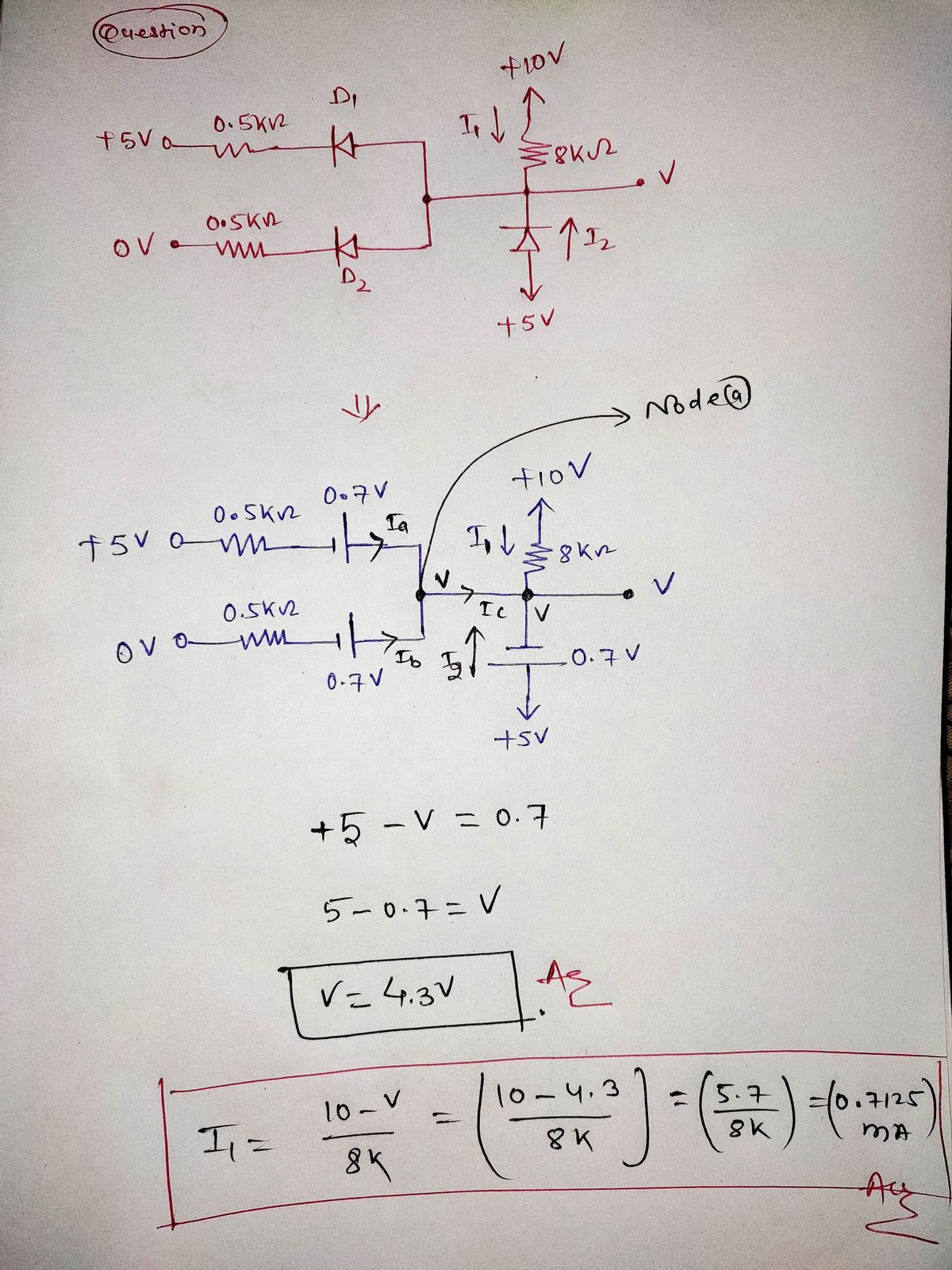
For the diode circuits shown below, find the values of I1, I2 and V indicated.
a) Using the constant-voltage-drop model (VD=0.7V):

Transcribed Image Text:### Diode Circuit Diagram
This schematic represents a diode-based circuit with two input voltages and multiple components, explained as follows:
- **Input Voltages:**
- **Top Input:** +5V through a 0.5 kΩ resistor.
- **Bottom Input:** 0V through a 0.5 kΩ resistor.
- **Diodes:**
- **D1** and **D2** are connected to the respective inputs.
- **Current Paths:**
- **I1:** Current flowing through an 8 kΩ resistor towards a +10V source.
- **I2:** Current flowing through a diode towards a +5V source.
- **Output Voltage:** Represented by V, located at the junction of D1, D2, and the 8 kΩ resistor.
### Explanation:
- The circuit diagram showcases how the input voltages are regulated using diodes (D1 and D2). These diodes allow current to flow in one direction, thereby preventing any reverse current which might alter the expected behavior of the circuit.
- The presence of resistors ensures that the current flowing through the circuit is within safe limits, preventing damage to the diodes and other components.
- The output voltage (V) is influenced by the potential differences and the operations of diodes and resistors in this setup. The currents I1 and I2 represent the two main paths of current flow due to the respective voltage sources.
This diagram can be integral in teaching concepts related to diode logic, voltage regulation, and circuit protection in electronics.
Expert Solution
Step 1

Step by step
Solved in 3 steps with 3 images

Knowledge Booster


Learn more about
Need a deep-dive on the concept behind this application? Look no further. Learn more about this topic, electrical-engineering and related others by exploring similar questions and additional content below.Recommended textbooks for you
Introductory Circuit Analysis (13th Edition)
Electrical Engineering
ISBN:
9780133923605
Author:
Robert L. Boylestad
Publisher:
PEARSON

Delmar's Standard Textbook Of Electricity
Electrical Engineering
ISBN:
9781337900348
Author:
Stephen L. Herman
Publisher:
Cengage Learning

Programmable Logic Controllers
Electrical Engineering
ISBN:
9780073373843
Author:
Frank D. Petruzella
Publisher:
McGraw-Hill Education
Introductory Circuit Analysis (13th Edition)
Electrical Engineering
ISBN:
9780133923605
Author:
Robert L. Boylestad
Publisher:
PEARSON
Delmar's Standard Textbook Of Electricity
Electrical Engineering
ISBN:
9781337900348
Author:
Stephen L. Herman
Publisher:
Cengage Learning
Programmable Logic Controllers
Electrical Engineering
ISBN:
9780073373843
Author:
Frank D. Petruzella
Publisher:
McGraw-Hill Education

Fundamentals of Electric Circuits
Electrical Engineering
ISBN:
9780078028229
Author:
Charles K Alexander, Matthew Sadiku
Publisher:
McGraw-Hill Education

Electric Circuits. (11th Edition)
Electrical Engineering
ISBN:
9780134746968
Author:
James W. Nilsson, Susan Riedel
Publisher:
PEARSON

Engineering Electromagnetics
Electrical Engineering
ISBN:
9780078028151
Author:
Hayt, William H. (william Hart), Jr, BUCK, John A.
Publisher:
Mcgraw-hill Education,