DU, F 2, www n A Circuit ез B -W₂ use the Constant vortage drop diode model with VD=07v. The R₂= 2102, where: V₁ = 20v², V₂ = 200, R₁, = 1 k₁², R₂=2x12 24=11√ (9) Defermine the states C(on or off) of D₁ and De Determine the vortage at node A and B 5050
DU, F 2, www n A Circuit ез B -W₂ use the Constant vortage drop diode model with VD=07v. The R₂= 2102, where: V₁ = 20v², V₂ = 200, R₁, = 1 k₁², R₂=2x12 24=11√ (9) Defermine the states C(on or off) of D₁ and De Determine the vortage at node A and B 5050

Introductory Circuit Analysis (13th Edition)
13th Edition
ISBN:9780133923605
Author:Robert L. Boylestad
Publisher:Robert L. Boylestad
Chapter1: Introduction
Section: Chapter Questions
Problem 1P: Visit your local library (at school or home) and describe the extent to which it provides literature...

Related questions
Question

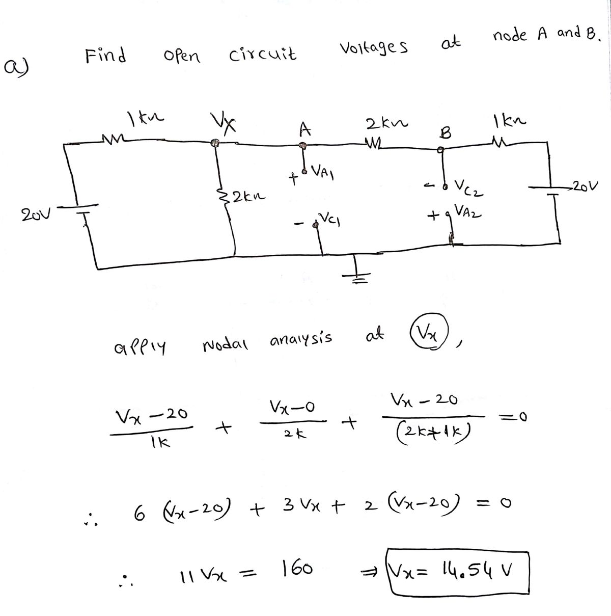
Transcribed Image Text:### Circuit Analysis Exercise
#### Circuit Diagram
The circuit consists of:
- Two voltage sources, \( V_1 \) and \( V_2 \).
- Four resistors, \( R_1 \), \( R_2 \), \( R_3 \), and \( R_4 \).
- Two diodes, \( D_1 \) and \( D_2 \).
- Nodes labeled \( A \) and \( B \).
#### Component Specifications
- \( V_1 = 20V \)
- \( V_2 = 20V \)
- \( R_1 = 1k\Omega \)
- \( R_2 = 2k\Omega \)
- \( R_3 = 2k\Omega \)
- \( R_4 = 1k\Omega \)
#### Instructions
1. **Use the Constant Voltage Drop Diode Model** with a diode forward voltage (\( V_D \)) of 0.7V.
2. **Tasks**:
- **(a)** Determine the states (ON or OFF) of diodes \( D_1 \) and \( D_2 \).
- **(b)** Determine the voltage at nodes \( A \) and \( B \).
Expert Solution
Step 1: Diode analysis

Step by step
Solved in 3 steps with 2 images

Knowledge Booster


Learn more about
Need a deep-dive on the concept behind this application? Look no further. Learn more about this topic, electrical-engineering and related others by exploring similar questions and additional content below.Recommended textbooks for you
Introductory Circuit Analysis (13th Edition)
Electrical Engineering
ISBN:
9780133923605
Author:
Robert L. Boylestad
Publisher:
PEARSON

Delmar's Standard Textbook Of Electricity
Electrical Engineering
ISBN:
9781337900348
Author:
Stephen L. Herman
Publisher:
Cengage Learning

Programmable Logic Controllers
Electrical Engineering
ISBN:
9780073373843
Author:
Frank D. Petruzella
Publisher:
McGraw-Hill Education
Introductory Circuit Analysis (13th Edition)
Electrical Engineering
ISBN:
9780133923605
Author:
Robert L. Boylestad
Publisher:
PEARSON
Delmar's Standard Textbook Of Electricity
Electrical Engineering
ISBN:
9781337900348
Author:
Stephen L. Herman
Publisher:
Cengage Learning
Programmable Logic Controllers
Electrical Engineering
ISBN:
9780073373843
Author:
Frank D. Petruzella
Publisher:
McGraw-Hill Education

Fundamentals of Electric Circuits
Electrical Engineering
ISBN:
9780078028229
Author:
Charles K Alexander, Matthew Sadiku
Publisher:
McGraw-Hill Education

Electric Circuits. (11th Edition)
Electrical Engineering
ISBN:
9780134746968
Author:
James W. Nilsson, Susan Riedel
Publisher:
PEARSON

Engineering Electromagnetics
Electrical Engineering
ISBN:
9780078028151
Author:
Hayt, William H. (william Hart), Jr, BUCK, John A.
Publisher:
Mcgraw-hill Education,