Determine the voltage across resistor R₂ in the circuit shown in the figure below. The battery emf is 30 V and the individual resistances are: R₁ = 12 02, R₂ = 702, R3 = 14 Q2, and R4 = 102. R₁ R₂ wwwww R3 R4 -N E
Determine the voltage across resistor R₂ in the circuit shown in the figure below. The battery emf is 30 V and the individual resistances are: R₁ = 12 02, R₂ = 702, R3 = 14 Q2, and R4 = 102. R₁ R₂ wwwww R3 R4 -N E

Related questions
Question

Transcribed Image Text:**Determine the Voltage Across Resistor R₂ in the Circuit**
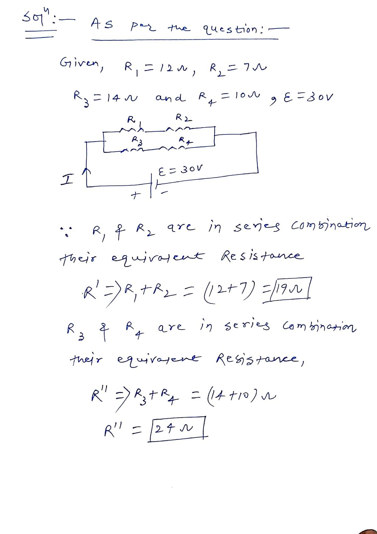
In the figure below, the goal is to determine the voltage across resistor \( R_2 \). The circuit consists of four resistors and a battery. The battery electromotive force (emf) is 30 V. The individual resistances are as follows:
- \( R_1 = 12 \, \Omega \)
- \( R_2 = 7 \, \Omega \)
- \( R_3 = 14 \, \Omega \)
- \( R_4 = 10 \, \Omega \)
**Circuit Diagram**
The circuit diagram shows a loop with the battery (emf, \( \mathcal{E} \)) connected to a combination of resistors in parallel and series:
- \( R_1 \) is in series with \( R_3 \).
- \( R_2 \) is in series with \( R_4 \).
- These two series combinations are in parallel with each other, connecting back to the battery.
**Calculated Voltage**
Using the given values and solving the circuit equations, the voltage across \( R_2 \) is found to be approximately 11.0526 V, with a margin of error of ±1%.
This exercise illustrates the principles of series and parallel resistor arrangements and the application of Kirchhoff's laws to calculate voltage drops across specific components in an electrical circuit.
Expert Solution
Step 1: Define given variables.
Using formula of combination of resistance.

Step by step
Solved in 3 steps with 2 images
