Determine the reactions hinges A and D exert on the frame and the force in each two force member. (Assume that the +x-axis is to the right and the +y-axis is up along the page. Enter ford 206 Ib/ft magnitude direction Select- magnitude direction Select- magnitude

Structural Analysis
6th Edition
ISBN:9781337630931
Author:KASSIMALI, Aslam.
Publisher:KASSIMALI, Aslam.
Chapter2: Loads On Structures
Section: Chapter Questions
Problem 1P
icon
Related questions
Question
### Problem Statement:

**Objective:** Determine the reactions that hinges A and D exert on the frame, and calculate the force in each two-force member.

**Assumptions:**
- The +x-axis is oriented to the right.
- The +y-axis is oriented upward.
- Forces are entered in pounds (lb).
- Use exact values without rounding intermediate calculations.

### Diagram Explanation:

A frame structure is shown with points A, B, C, D, E, and F. The structure consists of:

- A distributed load of 206 lb/ft applied between points B and C.
- Distances between points: 
  - A to E is 1 ft.
  - E to F is 2 ft.
  - F to D is 1 ft.

### Required Calculations:

Forces to be determined include:
- Reactions at A: 
  - \( \vec{A}_x \) and \( \vec{A}_y \) with their magnitudes and directions.
- Reactions at D:
  - \( \vec{D}_x \) and \( \vec{D}_y \) with their magnitudes and directions.
- Tension/compression in members:
  - \( F_{BE} \) and \( F_{CF} \) with their magnitudes and sense (tension or compression).

### Input Fields:

- Magnitude and direction for \( \vec{A}_x \).
- Magnitude and direction for \( \vec{A}_y \).
- Magnitude and direction for \( \vec{D}_x \).
- Magnitude and direction for \( \vec{D}_y \).
- Magnitude and sense for \( F_{BE} \).
- Magnitude and sense for \( F_{CF} \).
Transcribed Image Text:### Problem Statement: **Objective:** Determine the reactions that hinges A and D exert on the frame, and calculate the force in each two-force member. **Assumptions:** - The +x-axis is oriented to the right. - The +y-axis is oriented upward. - Forces are entered in pounds (lb). - Use exact values without rounding intermediate calculations. ### Diagram Explanation: A frame structure is shown with points A, B, C, D, E, and F. The structure consists of: - A distributed load of 206 lb/ft applied between points B and C. - Distances between points: - A to E is 1 ft. - E to F is 2 ft. - F to D is 1 ft. ### Required Calculations: Forces to be determined include: - Reactions at A: - \( \vec{A}_x \) and \( \vec{A}_y \) with their magnitudes and directions. - Reactions at D: - \( \vec{D}_x \) and \( \vec{D}_y \) with their magnitudes and directions. - Tension/compression in members: - \( F_{BE} \) and \( F_{CF} \) with their magnitudes and sense (tension or compression). ### Input Fields: - Magnitude and direction for \( \vec{A}_x \). - Magnitude and direction for \( \vec{A}_y \). - Magnitude and direction for \( \vec{D}_x \). - Magnitude and direction for \( \vec{D}_y \). - Magnitude and sense for \( F_{BE} \). - Magnitude and sense for \( F_{CF} \).
Expert Solution
Step 1

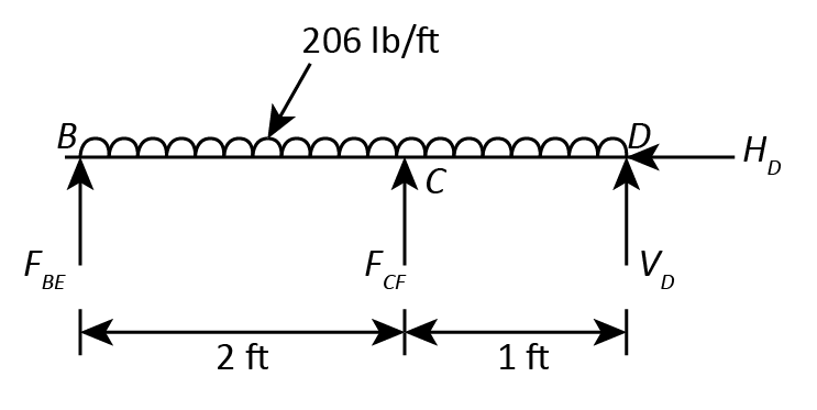
Member BCD.

The following figure shows the Free Body Diagram of Member BCD.
Civil Engineering homework question answer, step 1, image 1

The number of unknowns in the beam is 4.

The number of available equilibrium equations is 3.

Since, the number of unknowns is more than the number of equilibrium equations, the beam is statically indeterminate.

Adopt Moment Distribution Method to solve the beam.


Calculate the Fixed End Moments.

The fixed end moments for beam subjected to uniformly distributed load is given by,

MF=wL212

Therefore, the fixed end moments for span BC is,

MFBC=206 lb/ft2 ft212=68.67 lb-ft

MFCB=-206 lb/ft2 ft212=-68.67 lb-ft

The fixed end moments for span CD is,

MFCD=206 lb/ft1 ft212=17.167 lb-ft

MFDC=-206 lb/ft1 ft212=-17.167 lb-ft


Calculate the distributing factors for the beam spans.

Point

Span

Stiffness

Total Stiffness

Distribution Factor

C

BC

3EI/2=1.5EI

4.5EI

0.33

CD

3EI/1=3EI

0.67


Calculate the actual moments at the support


BC

CB

CD

DC

Distribution Factors

-

0.33

0.67


Fixed End Moments

68.67

-68.67

17.167

-17.167

Adjustment of Moment at B and D

-68.67

-

-

+17.167

Carryover Moment

-

-34.335

8.5835

-

Total Moment

0

-103.005

25.7505

0

Adjustment of Moment at B and C

0 +25.494 +51.761 0

Total Moment

0 77.511 +77.511 0


Calculate Support Reactions.

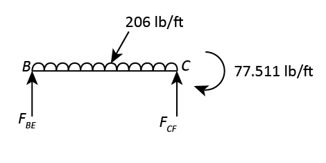
Calculate Support reaction for Span BC.

The following figure shows the Free Body Diagram of the Span BC.
Civil Engineering homework question answer, step 1, image 2

Consider moment of all the forces with respect to Point B.

Since the beam is in equilibrium, the sum of the moment at B will be zero.

MB=0FCF1×2 ft-206 lb/ft2 ft×2 ft2-77.511 lb-ft=02FCF1-412-77.511=0FCF1=489.5112=244.755 lb

The sum of all the forces in Y-direction is zero.

FY=0FCF1+FBE-206 lb/ft2 ft=0FBE=412-244.755=167.245 lb


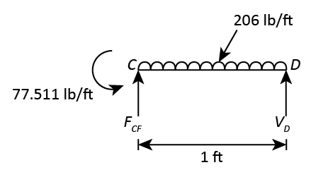
Calculate Support reaction for Span CD.

The following figure shows the Free Body Diagram of the Span CD.
Civil Engineering homework question answer, step 1, image 3

Consider moment of all the forces with respect to Point D.

Since the beam is in equilibrium, the sum of the moment at D will be zero.

MD=0FCF2×1 ft-206 lb/ft1 ft×1 ft2-77.511 lb-ft=0FCF2-103-77.511=0FCF2=180.511 lb

The sum of all the forces in Y-direction is zero.

FY=0FCF2+VD-206 lb/ft1 ft=0VD=206-180.511=25.489 lb

The sum of all the forces in X-direction is zero.

FX=0HD=0

trending now

Trending now

This is a popular solution!

steps

Step by step

Solved in 3 steps with 4 images

Blurred answer
Knowledge Booster
Equilibrium and support reactions
Learn more about
Need a deep-dive on the concept behind this application? Look no further. Learn more about this topic, civil-engineering and related others by exploring similar questions and additional content below.
Similar questions
Recommended textbooks for you
Structural Analysis
Structural Analysis
Civil Engineering
ISBN:
9781337630931
Author:
KASSIMALI, Aslam.
Publisher:
Cengage,
Structural Analysis (10th Edition)
Civil Engineering
ISBN:
9780134610672
Author:
Russell C. Hibbeler
Publisher:
PEARSON
Principles of Foundation Engineering (MindTap Cou…
Civil Engineering
ISBN:
9781337705028
Author:
Braja M. Das, Nagaratnam Sivakugan
Publisher:
Cengage Learning
Fundamentals of Structural Analysis
Civil Engineering
ISBN:
9780073398006
Author:
Kenneth M. Leet Emeritus, Chia-Ming Uang, Joel Lanning
Publisher:
McGraw-Hill Education
Sustainable Energy
Sustainable Energy
Civil Engineering
ISBN:
9781337551663
Author:
DUNLAP, Richard A.
Publisher:
Cengage,
Traffic and Highway Engineering
Civil Engineering
ISBN:
9781305156241
Author:
Garber, Nicholas J.
Publisher:
Cengage Learning