determine the output voltage

Introductory Circuit Analysis (13th Edition)
13th Edition
ISBN:9780133923605
Author:Robert L. Boylestad
Publisher:Robert L. Boylestad
Chapter1: Introduction
Section: Chapter Questions
Problem 1P: Visit your local library (at school or home) and describe the extent to which it provides literature...

Related questions
Question
determine the output voltage

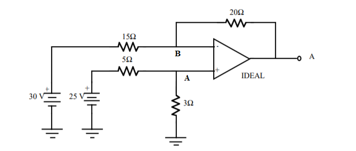
Transcribed Image Text:This diagram represents an electrical circuit featuring an operational amplifier configured in a specific arrangement. Below is a detailed explanation of the components and connections:
1. **Voltage Sources**:
- A 30V voltage source and a 25V voltage source are connected in parallel at the input section of the circuit.
2. **Resistors**:
- A 15Ω resistor is connected in series with the 30V source.
- A 5Ω resistor follows in series after the 15Ω resistor.
- There is a 3Ω resistor connected to the ground from the non-inverting input of the operational amplifier (op-amp).
- A 20Ω resistor connects the output to the inverting input, likely forming a feedback loop.
3. **Operational Amplifier (Op-Amp)**:
- The op-amp is labeled as "IDEAL," implying it follows ideal op-amp assumptions, such as infinite input impedance, zero output impedance, and infinite gain.
- The inverting input (-) receives feedback from the output through the 20Ω resistor.
- The non-inverting input (+) is directly connected to the series arrangement of the voltage sources and resistors.
4. **Output**:
- The output, labeled as point "A," provides the resultant voltage or signal after processing by the op-amp and associated components.
This circuit demonstrates the use of an op-amp in a configuration that likely forms a summing amplifier, where multiple voltages are combined, processed through the resistor network and op-amp to produce a specified output at point A.
Expert Solution
Step 1
Given circuit is consist of the operational amplifier.

Step by step
Solved in 2 steps with 3 images

Knowledge Booster


Learn more about
Need a deep-dive on the concept behind this application? Look no further. Learn more about this topic, electrical-engineering and related others by exploring similar questions and additional content below.Recommended textbooks for you
Introductory Circuit Analysis (13th Edition)
Electrical Engineering
ISBN:
9780133923605
Author:
Robert L. Boylestad
Publisher:
PEARSON

Delmar's Standard Textbook Of Electricity
Electrical Engineering
ISBN:
9781337900348
Author:
Stephen L. Herman
Publisher:
Cengage Learning

Programmable Logic Controllers
Electrical Engineering
ISBN:
9780073373843
Author:
Frank D. Petruzella
Publisher:
McGraw-Hill Education
Introductory Circuit Analysis (13th Edition)
Electrical Engineering
ISBN:
9780133923605
Author:
Robert L. Boylestad
Publisher:
PEARSON
Delmar's Standard Textbook Of Electricity
Electrical Engineering
ISBN:
9781337900348
Author:
Stephen L. Herman
Publisher:
Cengage Learning
Programmable Logic Controllers
Electrical Engineering
ISBN:
9780073373843
Author:
Frank D. Petruzella
Publisher:
McGraw-Hill Education

Fundamentals of Electric Circuits
Electrical Engineering
ISBN:
9780078028229
Author:
Charles K Alexander, Matthew Sadiku
Publisher:
McGraw-Hill Education

Electric Circuits. (11th Edition)
Electrical Engineering
ISBN:
9780134746968
Author:
James W. Nilsson, Susan Riedel
Publisher:
PEARSON

Engineering Electromagnetics
Electrical Engineering
ISBN:
9780078028151
Author:
Hayt, William H. (william Hart), Jr, BUCK, John A.
Publisher:
Mcgraw-hill Education,