Determine the forces acting on the ground and the torque, T₁2, to maintain static equilibrium for the four-bar linkage shown in Figure using both graphical and analytical methods. R₁0,=87.5mm, R₂4=R30₁=150mm, co. 100 mm, Rp.175 mm, and Ro.o.=175 mm, De B 3 P 4 105.1° 240° A 2 T12 -152.4° 04
Determine the forces acting on the ground and the torque, T₁2, to maintain static equilibrium for the four-bar linkage shown in Figure using both graphical and analytical methods. R₁0,=87.5mm, R₂4=R30₁=150mm, co. 100 mm, Rp.175 mm, and Ro.o.=175 mm, De B 3 P 4 105.1° 240° A 2 T12 -152.4° 04

Elements Of Electromagnetics
7th Edition
ISBN:9780190698614
Author:Sadiku, Matthew N. O.
Publisher:Sadiku, Matthew N. O.
ChapterMA: Math Assessment
Section: Chapter Questions
Problem 1.1MA

Related questions

Question
P=222.5 N

Transcribed Image Text:**Text Transcription:**
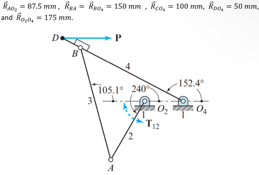
Determine the forces acting on the ground and the torque, \( T_{12} \), to maintain static equilibrium for the four-bar linkage shown in Figure using both graphical and analytical methods.
\(\vec{R}_{A,O} = 87.5 \, \text{mm}, \, \vec{R}_{B,A} = \vec{R}_{B,O_2} = 150 \, \text{mm}, \, \vec{R}_{C,O} = 100 \, \text{mm}, \, \vec{R}_{D,O} = 175 \, \text{mm}, \, \text{and} \, \vec{R}_{O_4,O_2} = 175 \, \text{mm}.\)
**Diagram Explanation:**
The diagram depicts a four-bar linkage system. The system includes the following key components:
1. **Points:**
- Point A, B, C, D, O₂, O₄ are labeled to indicate specific locations on the linkage system.
2. **Bars:**
- Four bars are labeled 1 through 4, which form the linkage.
3. **Forces and Directions:**
- An arrow labeled \( P \) is shown acting horizontally to the right at point D.
- The torque \( T_{12} \) is indicated at joint O₂ with an arrow in a clockwise direction.
4. **Angles:**
- An angle of 105.1° is noted between lines extending from points A to O₂ and B to A.
- Another angle, 152.4°, is between the horizontal line from point O₂ to O₄ and a line from O₂ to B.
- A circle with an angle of 240° is inscribed around point O₂.
5. **Structural Supports:**
- The diagram shows fixed pivot points at O₂ and O₄, indicated by hardware symbols on horizontal lines.
This figure is used to determine the static forces required for maintaining equilibrium in this particular four-bar mechanism, using given lengths and angles associated with the linkage configuration.
Expert Solution
Step 1: Given data
The problem must be solved both analytically and visually.

Step by step
Solved in 3 steps with 5 images

Knowledge Booster


Learn more about
Need a deep-dive on the concept behind this application? Look no further. Learn more about this topic, mechanical-engineering and related others by exploring similar questions and additional content below.Recommended textbooks for you
Elements Of Electromagnetics
Mechanical Engineering
ISBN:
9780190698614
Author:
Sadiku, Matthew N. O.
Publisher:
Oxford University Press

Mechanics of Materials (10th Edition)
Mechanical Engineering
ISBN:
9780134319650
Author:
Russell C. Hibbeler
Publisher:
PEARSON

Thermodynamics: An Engineering Approach
Mechanical Engineering
ISBN:
9781259822674
Author:
Yunus A. Cengel Dr., Michael A. Boles
Publisher:
McGraw-Hill Education
Elements Of Electromagnetics
Mechanical Engineering
ISBN:
9780190698614
Author:
Sadiku, Matthew N. O.
Publisher:
Oxford University Press
Mechanics of Materials (10th Edition)
Mechanical Engineering
ISBN:
9780134319650
Author:
Russell C. Hibbeler
Publisher:
PEARSON
Thermodynamics: An Engineering Approach
Mechanical Engineering
ISBN:
9781259822674
Author:
Yunus A. Cengel Dr., Michael A. Boles
Publisher:
McGraw-Hill Education

Control Systems Engineering
Mechanical Engineering
ISBN:
9781118170519
Author:
Norman S. Nise
Publisher:
WILEY

Mechanics of Materials (MindTap Course List)
Mechanical Engineering
ISBN:
9781337093347
Author:
Barry J. Goodno, James M. Gere
Publisher:
Cengage Learning

Engineering Mechanics: Statics
Mechanical Engineering
ISBN:
9781118807330
Author:
James L. Meriam, L. G. Kraige, J. N. Bolton
Publisher:
WILEY