Design a VHDL test bench to verify the functional operation of the system in the following figure using report and assert statements. Your test bench should drive in each input code for the vector ABCD in the order they appear in the truth table (i.e., "0000", "0001", "0010", ...). Have your test bench change the input pattern every 10 ns using the wait for statement within your stimulus process. Use the report and assert statements to output a message on the status of each test to the simulation transcript window. For each input vector, create a message that indicates the current input vector being tested, the resulting output of your DUT, and whether the DUT output is correct. NOTE: You will need to design the SystemJ.vhd system. Use a case statement to implement the logic. SystemJ.vhd F = EAB.C.D(4,5,7,12,13,15) ABCD Deliverables: Simulate your model and test bench using ModelSim. You are to upload your VHDL test bench file (SystemJ_TB.vhd) and a screenshot of your report outputs in the transcript portion of the ModelSim window (name it transcript_8_4_4.jpg) to the HW 8.4 Assignment Folder. Make sure to resize the transcript window so that I can tell if it is working.
Design a VHDL test bench to verify the functional operation of the system in the following figure using report and assert statements. Your test bench should drive in each input code for the vector ABCD in the order they appear in the truth table (i.e., "0000", "0001", "0010", ...). Have your test bench change the input pattern every 10 ns using the wait for statement within your stimulus process. Use the report and assert statements to output a message on the status of each test to the simulation transcript window. For each input vector, create a message that indicates the current input vector being tested, the resulting output of your DUT, and whether the DUT output is correct. NOTE: You will need to design the SystemJ.vhd system. Use a case statement to implement the logic. SystemJ.vhd F = EAB.C.D(4,5,7,12,13,15) ABCD Deliverables: Simulate your model and test bench using ModelSim. You are to upload your VHDL test bench file (SystemJ_TB.vhd) and a screenshot of your report outputs in the transcript portion of the ModelSim window (name it transcript_8_4_4.jpg) to the HW 8.4 Assignment Folder. Make sure to resize the transcript window so that I can tell if it is working.

Introductory Circuit Analysis (13th Edition)
13th Edition
ISBN:9780133923605
Author:Robert L. Boylestad
Publisher:Robert L. Boylestad
Chapter1: Introduction
Section: Chapter Questions
Problem 1P: Visit your local library (at school or home) and describe the extent to which it provides literature...

Related questions

Question

Transcribed Image Text:HW 8.4 - Test Benches
Problem 8.4.4
Design a VHDL test bench to verify the functional operation of the system in the following figure using report and assert statements. Your test bench should drive in each input
code for the vector ABCD in the order they appear in the truth table (i.e., "0000", “O001", “0010", ...). Have your test bench change the input pattern every 10 ns using the wait for
statement within your stimulus process. Use the report and assert statements to output a message on the status of each test to the simulation transcript window. For each
input vector, create a message that indicates the current input vector being tested, the resulting output of your DUT, and whether the DUT output is correct.
NOTE: You will need to design the SystemJ.vhd system. Use a case statement to implement the logic.
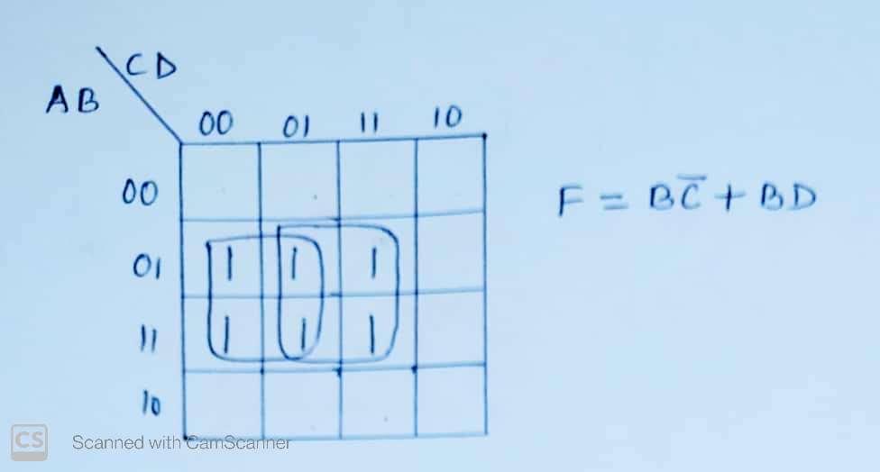
SystemJ.vhd
F = EAB.C.D(4,5,7,12,13,15)
4
HABCD
F
Deliverables: Simulate your model and test bench using ModelSim. You are to upload your VHDL test bench file (SystemJ_TB.vhd) and a screenshot of your report outputs in the
transcript portion of the ModelSim window (name it transcript_8_4_4.jpg) to the HW 8.4 Assignment Folder. Make sure to resize the transcript window so that I can tell if it is
working.
Expert Solution
Step 1

Trending now
This is a popular solution!

Step by step
Solved in 3 steps with 2 images

Knowledge Booster


Learn more about
Need a deep-dive on the concept behind this application? Look no further. Learn more about this topic, electrical-engineering and related others by exploring similar questions and additional content below.Recommended textbooks for you
Introductory Circuit Analysis (13th Edition)
Electrical Engineering
ISBN:
9780133923605
Author:
Robert L. Boylestad
Publisher:
PEARSON

Delmar's Standard Textbook Of Electricity
Electrical Engineering
ISBN:
9781337900348
Author:
Stephen L. Herman
Publisher:
Cengage Learning

Programmable Logic Controllers
Electrical Engineering
ISBN:
9780073373843
Author:
Frank D. Petruzella
Publisher:
McGraw-Hill Education
Introductory Circuit Analysis (13th Edition)
Electrical Engineering
ISBN:
9780133923605
Author:
Robert L. Boylestad
Publisher:
PEARSON
Delmar's Standard Textbook Of Electricity
Electrical Engineering
ISBN:
9781337900348
Author:
Stephen L. Herman
Publisher:
Cengage Learning
Programmable Logic Controllers
Electrical Engineering
ISBN:
9780073373843
Author:
Frank D. Petruzella
Publisher:
McGraw-Hill Education

Fundamentals of Electric Circuits
Electrical Engineering
ISBN:
9780078028229
Author:
Charles K Alexander, Matthew Sadiku
Publisher:
McGraw-Hill Education

Electric Circuits. (11th Edition)
Electrical Engineering
ISBN:
9780134746968
Author:
James W. Nilsson, Susan Riedel
Publisher:
PEARSON

Engineering Electromagnetics
Electrical Engineering
ISBN:
9780078028151
Author:
Hayt, William H. (william Hart), Jr, BUCK, John A.
Publisher:
Mcgraw-hill Education,