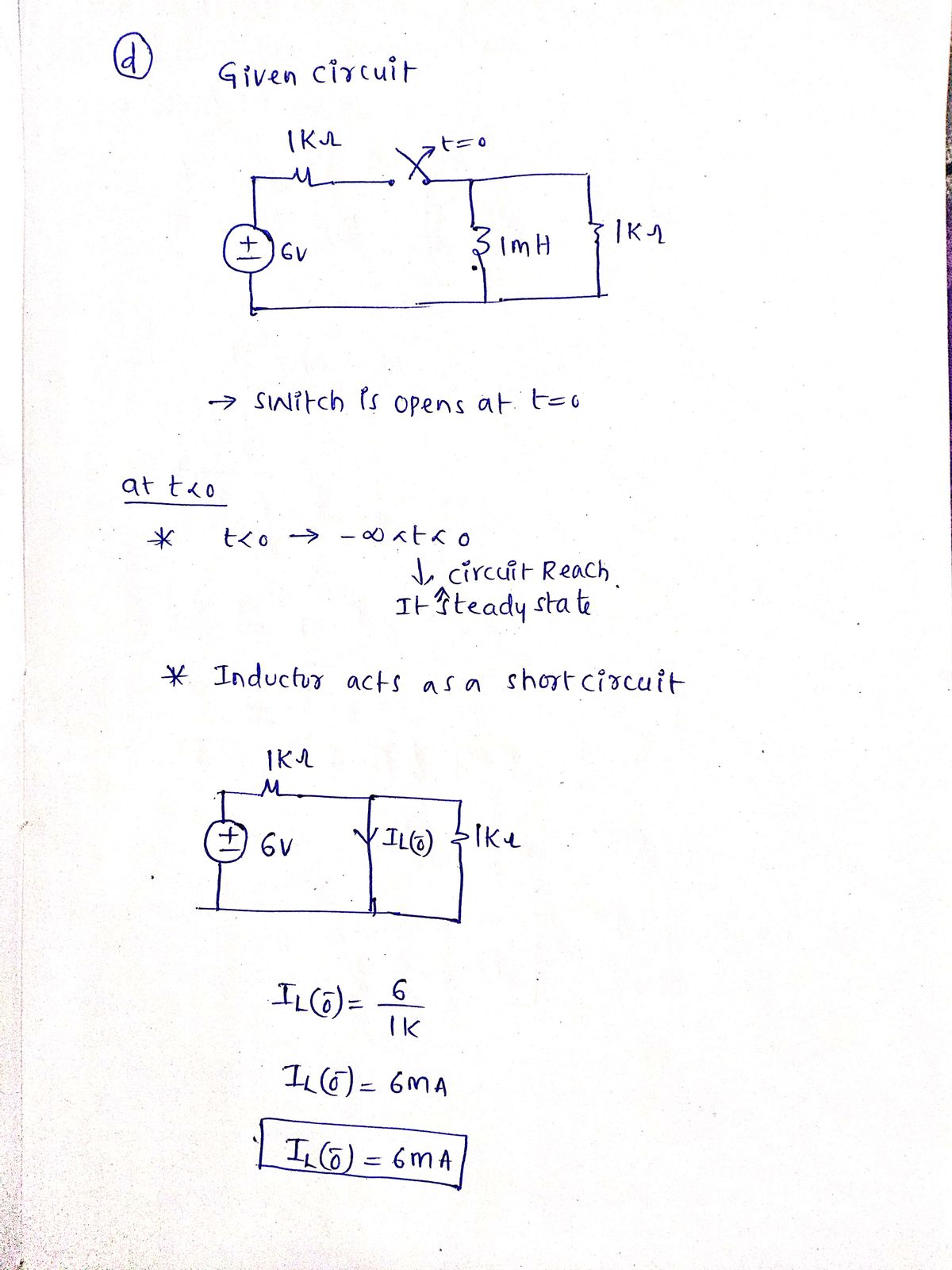
(d) 6 V +1 1 kQ www 1 mH 1 ΚΩ after being closed, switch opens at t = 0
(d) 6 V +1 1 kQ www 1 mH 1 ΚΩ after being closed, switch opens at t = 0
Introductory Circuit Analysis (13th Edition)
13th Edition
ISBN:9780133923605
Author:Robert L. Boylestad
Publisher:Robert L. Boylestad
Chapter1: Introduction
Section: Chapter Questions
Problem 1P: Visit your local library (at school or home) and describe the extent to which it provides literature...
Related questions
Question
(Handwrite, more details)Calculate and sketch the zero-input response (the transient response with no input source) for ? > 0 of each circuit below. Answers should be an expression for ?(?) across a capacitor or ?(?) through an inductor, the time constant, and a simple sketch showing the transient response with the initial and final values and time constant labeled. Don’t forget to include units

Transcribed Image Text:**Transcription and Explanation: Electrical Circuit Diagrams**
This educational resource features a series of electrical circuit diagrams focusing on initial conditions and switch operations within RC (resistor-capacitor) and RL (resistor-inductor) circuits.
**Diagram (a):**
- Features two 1 kΩ resistors and a 1 µF capacitor.
- The initial voltage across the capacitor, \(v(0)\), is specified as 6V.
**Diagram (b):**
- Shows two 1 kΩ resistors and a 1 mH inductor.
- The initial current through the inductor, \(i(0)\), is indicated as 6 mA.
**Diagram (c):**
- Describes an RC circuit with a switch, a 1 kΩ resistor, and a 1 µF capacitor, connected to a 6V voltage source.
- The text indicates that after being closed, the switch opens at \(t = 0\).
**Diagram (d):**
- Depicts an RL circuit with a switch, two 1 kΩ resistors, and a 1 mH inductor, also connected to a 6V voltage source.
- Similar to Diagram (c), the switch opens at \(t = 0\) after being closed.
**Explanation:**
- These diagrams illustrate different types of transient analysis in electrical circuits. Initially, conditions for capacitor voltage and inductor current are given, helping analyze how these elements behave dynamically when changes occur in the circuit, such as a switch operation.
- For both circuit types, understanding the transient response is crucial in various applications like signal processing and power management.
Expert Solution
Step 1

Step by step
Solved in 2 steps with 2 images

Recommended textbooks for you

Introductory Circuit Analysis (13th Edition)
Electrical Engineering
ISBN:
9780133923605
Author:
Robert L. Boylestad
Publisher:
PEARSON

Delmar's Standard Textbook Of Electricity
Electrical Engineering
ISBN:
9781337900348
Author:
Stephen L. Herman
Publisher:
Cengage Learning

Programmable Logic Controllers
Electrical Engineering
ISBN:
9780073373843
Author:
Frank D. Petruzella
Publisher:
McGraw-Hill Education

Introductory Circuit Analysis (13th Edition)
Electrical Engineering
ISBN:
9780133923605
Author:
Robert L. Boylestad
Publisher:
PEARSON

Delmar's Standard Textbook Of Electricity
Electrical Engineering
ISBN:
9781337900348
Author:
Stephen L. Herman
Publisher:
Cengage Learning

Programmable Logic Controllers
Electrical Engineering
ISBN:
9780073373843
Author:
Frank D. Petruzella
Publisher:
McGraw-Hill Education

Fundamentals of Electric Circuits
Electrical Engineering
ISBN:
9780078028229
Author:
Charles K Alexander, Matthew Sadiku
Publisher:
McGraw-Hill Education

Electric Circuits. (11th Edition)
Electrical Engineering
ISBN:
9780134746968
Author:
James W. Nilsson, Susan Riedel
Publisher:
PEARSON

Engineering Electromagnetics
Electrical Engineering
ISBN:
9780078028151
Author:
Hayt, William H. (william Hart), Jr, BUCK, John A.
Publisher:
Mcgraw-hill Education,