Consider the circuit below. C, = 200 mF R, = 11 kn EV = 24 V R, = 11 kQ EV - 24 V R = 33 kn R, = 33 kn (a) What is the RC time constant of the circuit (in s)? (b) What is the initial current (in A) in the circuit once the switch is closed? (c) How much time (in s) passes between the instant the switch is closed and the time the current has reached half of the initial current?
Consider the circuit below. C, = 200 mF R, = 11 kn EV = 24 V R, = 11 kQ EV - 24 V R = 33 kn R, = 33 kn (a) What is the RC time constant of the circuit (in s)? (b) What is the initial current (in A) in the circuit once the switch is closed? (c) How much time (in s) passes between the instant the switch is closed and the time the current has reached half of the initial current?
Related questions
Question
![**Circuit Analysis Problem**
Consider the circuit below:
- **Capacitor:**
- \( C_1 = 200 \, \text{mF} \)
- **Voltage Sources:**
- \( V_1 = 24 \, \text{V} \)
- \( V_2 = 24 \, \text{V} \)
- **Resistors:**
- \( R_1 = 11 \, \text{k}\Omega \)
- \( R_2 = 11 \, \text{k}\Omega \)
- \( R_3 = 33 \, \text{k}\Omega \)
- \( R_4 = 33 \, \text{k}\Omega \)
**Problems to Solve:**
(a) *What is the RC time constant of the circuit (in seconds)?*
\[ \boxed{\text{ }} \, \text{s} \]
(b) *What is the initial current (in amperes) in the circuit once the switch is closed?*
\[ \boxed{\text{ }} \, \text{A} \]
(c) *How much time (in seconds) passes between the instant the switch is closed and the time the current has reached half of the initial current?*
\[ \boxed{\text{ }} \, \text{s} \]
**Diagram Description:**
The circuit diagram includes a capacitor \( C_1 \) at the top, connected to a switch. The circuit has two voltage sources, \( V_1 \) and \( V_2 \), each supplying 24V. Four resistors, \( R_1 \), \( R_2 \), \( R_3 \), and \( R_4 \) are placed in the circuit with specified resistance values. Resistors \( R_1 \) and \( R_2 \) both have resistances of 11 kΩ, whereas \( R_3 \) and \( R_4 \) each have resistances of 33 kΩ.](/v2/_next/image?url=https%3A%2F%2Fcontent.bartleby.com%2Fqna-images%2Fquestion%2Fa7490bd9-e0f2-4b79-93ee-58f1abe77868%2Fb8fde6f0-ea74-4287-8d47-275fccf257b9%2Fu1k3r4_processed.jpeg&w=3840&q=75)
Transcribed Image Text:**Circuit Analysis Problem**
Consider the circuit below:
- **Capacitor:**
- \( C_1 = 200 \, \text{mF} \)
- **Voltage Sources:**
- \( V_1 = 24 \, \text{V} \)
- \( V_2 = 24 \, \text{V} \)
- **Resistors:**
- \( R_1 = 11 \, \text{k}\Omega \)
- \( R_2 = 11 \, \text{k}\Omega \)
- \( R_3 = 33 \, \text{k}\Omega \)
- \( R_4 = 33 \, \text{k}\Omega \)
**Problems to Solve:**
(a) *What is the RC time constant of the circuit (in seconds)?*
\[ \boxed{\text{ }} \, \text{s} \]
(b) *What is the initial current (in amperes) in the circuit once the switch is closed?*
\[ \boxed{\text{ }} \, \text{A} \]
(c) *How much time (in seconds) passes between the instant the switch is closed and the time the current has reached half of the initial current?*
\[ \boxed{\text{ }} \, \text{s} \]
**Diagram Description:**
The circuit diagram includes a capacitor \( C_1 \) at the top, connected to a switch. The circuit has two voltage sources, \( V_1 \) and \( V_2 \), each supplying 24V. Four resistors, \( R_1 \), \( R_2 \), \( R_3 \), and \( R_4 \) are placed in the circuit with specified resistance values. Resistors \( R_1 \) and \( R_2 \) both have resistances of 11 kΩ, whereas \( R_3 \) and \( R_4 \) each have resistances of 33 kΩ.
Expert Solution
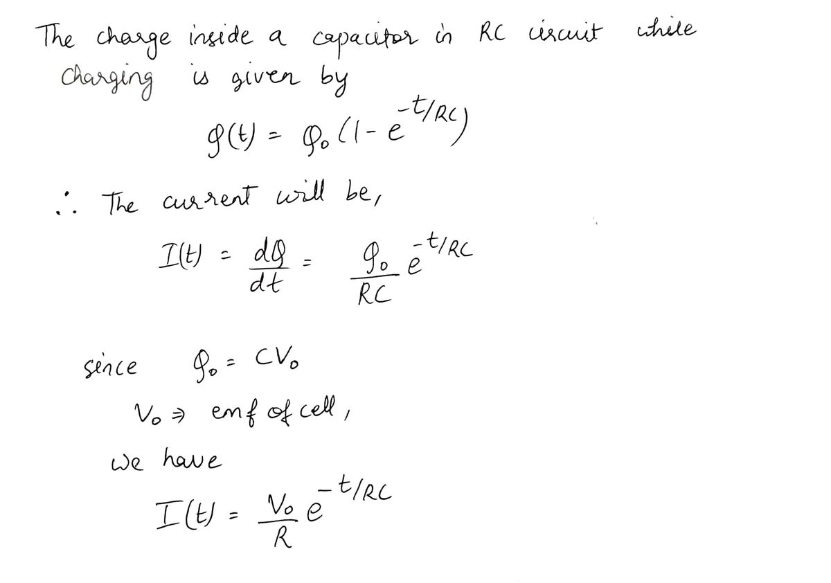
Step 1

Step by step
Solved in 3 steps with 3 images
