Consider following circuit with R1 = 62 Ω, R2 = 11 Ω, R3 = 62 / 10 Ω, R4 = 11/10 Ω and and ξ=11 V c. Write Kirchhoff’s potential difference rule for left loop d. Write Kirchhoff’s potential difference rule for right loop
Consider following circuit with R1 = 62 Ω, R2 = 11 Ω, R3 = 62 / 10 Ω, R4 = 11/10 Ω and and ξ=11 V c. Write Kirchhoff’s potential difference rule for left loop d. Write Kirchhoff’s potential difference rule for right loop

College Physics
1st Edition
ISBN:9781938168000
Author:Paul Peter Urone, Roger Hinrichs
Publisher:Paul Peter Urone, Roger Hinrichs
Chapter19: Electric Potential And Electric Field
Section: Chapter Questions
Problem 12PE: Construct Your Own Problem Consider a battery used to supply energy to a cellular phone. Construct a...

Related questions
Question
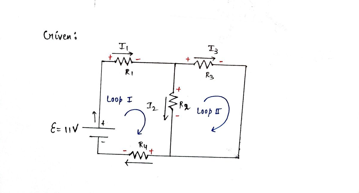
Consider following circuit with R1 = 62 Ω, R2 = 11 Ω, R3 = 62 / 10 Ω, R4 = 11/10 Ω and and ξ=11 V
c. Write Kirchhoff’s potential difference rule for left loop
d. Write Kirchhoff’s potential difference rule for right loop

Transcribed Image Text:### Electrical Circuit Diagram
This diagram illustrates a basic electrical circuit containing four resistors and a voltage source. The circuit is arranged as follows:
- **Voltage Source**: Positioned on the left side of the diagram between points **a** and **b**, it provides electrical energy to the circuit.
- **Resistors**:
- **R1**: Connected between the voltage source and point **b**.
- **R2**: Situated vertically between points **b** and **c**.
- **R3**: Aligned horizontally between points **b** and **e**.
- **R4**: Located between points **a** and **c**, in parallel with the voltage source.
- **Current Flows**:
- **i1**: The electric current passing through resistor **R1**.
- **i2**: The electric current passing through resistor **R2**.
- **i3**: The electric current passing through resistor **R3**.
Arrows indicate the direction of current flow for each resistor, demonstrating how the electrical current is routed through the circuit. The loop formed in the circuit shows a closed path, ensuring that current can continuously flow when the circuit is powered. This diagram can be used to analyze and understand the behavior of electrical components in series and parallel configurations.
Expert Solution
Step 1

Step by step
Solved in 3 steps with 3 images

Knowledge Booster


Learn more about
Need a deep-dive on the concept behind this application? Look no further. Learn more about this topic, physics and related others by exploring similar questions and additional content below.Recommended textbooks for you
College Physics
Physics
ISBN:
9781938168000
Author:
Paul Peter Urone, Roger Hinrichs
Publisher:
OpenStax College

Glencoe Physics: Principles and Problems, Student…
Physics
ISBN:
9780078807213
Author:
Paul W. Zitzewitz
Publisher:
Glencoe/McGraw-Hill

College Physics
Physics
ISBN:
9781938168000
Author:
Paul Peter Urone, Roger Hinrichs
Publisher:
OpenStax College
Glencoe Physics: Principles and Problems, Student…
Physics
ISBN:
9780078807213
Author:
Paul W. Zitzewitz
Publisher:
Glencoe/McGraw-Hill

Physics for Scientists and Engineers, Technology …
Physics
ISBN:
9781305116399
Author:
Raymond A. Serway, John W. Jewett
Publisher:
Cengage Learning

Physics for Scientists and Engineers
Physics
ISBN:
9781337553278
Author:
Raymond A. Serway, John W. Jewett
Publisher:
Cengage Learning

Physics for Scientists and Engineers with Modern …
Physics
ISBN:
9781337553292
Author:
Raymond A. Serway, John W. Jewett
Publisher:
Cengage Learning