23) The floor area shown in Fig. 11 is 30 ft x 16 ft. The tributary area of Beam B1 is equal to A. 128 ft² B 352 ft² 176 ft² D. 64 f
23) The floor area shown in Fig. 11 is 30 ft x 16 ft. The tributary area of Beam B1 is equal to A. 128 ft² B 352 ft² 176 ft² D. 64 f
Chapter2: Loads On Structures
Section: Chapter Questions
Problem 1P
Related questions
Question
Please explain how to do question 23 in full detail. Can you also explain how to solve problem 24, Thank you I would really appreicate it

Transcribed Image Text:23) The floor area shown in Fig. 11 is 30 ft x 16 ft. The tributary area of beam B1 is equal to:
A. 128 ft²
B. 352 ft²
C. 176 ft²
D. 64 ft²
The correct answer is marked: C. 176 ft²

Transcribed Image Text:### Structural Beam Load Calculation
#### Problem Statement
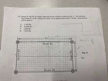
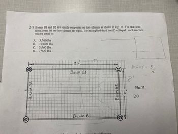
Beams B1 and B2 are simply supported on the columns as shown in Fig. 11. The reactions from Beam B1 on the columns are equal for the applied dead load D = 90 psf. Each reaction will be equal to:
- A. 5760 lbs
- B. 10,800 lbs
- C. 3,960 lbs
- D. 7,920 lbs
#### Diagram Description (Fig. 11)
- The diagram presents a rectangular grid with two major beams labeled as "Beam B1" and "Beam B2."
- The rectangle's dimensions are marked as 30 units and 16 units on adjacent sides.
- Four support columns are depicted at each corner of the rectangle.
- The rectangle contains grid lines that likely represent evenly distributed loads.
#### Diagram Annotations
- "Beam B2" is labeled along the longer side of the rectangle.
- "Beam B1" is running parallel to "Beam B2" across the shorter distance between columns.
- Additional annotation on the right indicates "21" and a reference to "teams = 18 x 1."
- The placement of beams in the grid suggests a load distribution analysis.
#### Load Distribution
The beams distribute loads evenly across their lengths, affecting each supporting column equally. The primary task is to determine the equal reaction at each column due to the specified applied load.
### Instructions for Students
Using principles of civil engineering and structural analysis, calculate the equal reaction force at each column utilizing the given diagram dimensions, load distribution, and options provided. Consider concepts such as balancing forces and moment distribution in your analysis.
### Answer Options
Choose the correct calculation for the column reaction from the provided options.
- A. 5760 lbs
- B. 10,800 lbs
- C. 3,960 lbs
- D. 7,920 lbs
Use the diagram and problem statement to assist in deriving the solution.
Expert Solution
Step 1
KINDLY NOTE: As per our guidelines, we are supposed to answer the first question in case multiple questions unless specified otherwise. Thus, in this case following the said guideline question 23 will be solved.
Objective: To determine the tributary area for beam B1.
The tributary area of a beam is the area of a floor/roof that causes the load to act on that particular beam.
Step by step
Solved in 2 steps with 1 images

Follow-up Questions
Read through expert solutions to related follow-up questions below.
Follow-up Question
Answer B is not correct please answer with a full explantion if youre sure of the answer

Transcribed Image Text:### Educational Content on Beam Reactions
**Diagram Explanation:**
The diagram, labeled as Fig. 11, depicts a rectangular framework composed of two beams, B1 and B2, which are simply supported by columns at each corner. The framework dimensions are specified as 21 feet in length along the longer side and 16 feet along the shorter side. Each side of the frame is denoted by evenly spaced grid lines, which likely represent measurement units in feet. The beams are identified in the diagram as "Beam B1" and "Beam B2."
**Problem Statement:**
The task is to determine the reactions from Beam B1 on the columns when the columns are equally loaded. The applied dead load is given as D = 90 psf (pounds per square foot). The options for the reactions are provided as follows:
- A. 5,760 lbs
- B. 10,080 lbs
- C. 3,960 lbs
- D. 7,920 lbs
To solve this, one would typically use principles of static equilibrium, considering the applied loads and supports.
**Calculations/Annotations:**
There is a handwritten annotation on the right side of the image which calculates the area using the given dimensions:
- Length (21 feet) x Width (16 feet) = Area
These calculations are essential to derive the total load based on the area and the given load per unit area (90 psf).
This scenario is typical in structural engineering education, helping students understand the distribution of loads and reaction calculations in simple beam and column systems.
Solution
Follow-up Question
Thank you, can you now please answer number 24

Transcribed Image Text:Ⓡ
24) Beams B1 and B2 are simply supported on the columns as shown in Fig. 11. The reactions
from Beam B1 on the columns are equal. For an applied dead load D = 90 psf, each reaction
will be equal to:
A. 5,760 lbs
B.
10,800 lbs
C.
D.
H
BeamBz
3,960 lbs
7,920 lbs
30
Beam Bl
Beam Bl
the following.
Beam B2
AL
16
· tanus = 8.
8₁
Fig. 11
30
colx
Solution
Knowledge Booster
Learn more about
Need a deep-dive on the concept behind this application? Look no further. Learn more about this topic, civil-engineering and related others by exploring similar questions and additional content below.Recommended textbooks for you


Structural Analysis (10th Edition)
Civil Engineering
ISBN:
9780134610672
Author:
Russell C. Hibbeler
Publisher:
PEARSON

Principles of Foundation Engineering (MindTap Cou…
Civil Engineering
ISBN:
9781337705028
Author:
Braja M. Das, Nagaratnam Sivakugan
Publisher:
Cengage Learning


Structural Analysis (10th Edition)
Civil Engineering
ISBN:
9780134610672
Author:
Russell C. Hibbeler
Publisher:
PEARSON

Principles of Foundation Engineering (MindTap Cou…
Civil Engineering
ISBN:
9781337705028
Author:
Braja M. Das, Nagaratnam Sivakugan
Publisher:
Cengage Learning

Fundamentals of Structural Analysis
Civil Engineering
ISBN:
9780073398006
Author:
Kenneth M. Leet Emeritus, Chia-Ming Uang, Joel Lanning
Publisher:
McGraw-Hill Education


Traffic and Highway Engineering
Civil Engineering
ISBN:
9781305156241
Author:
Garber, Nicholas J.
Publisher:
Cengage Learning