Ans: Vo = 10 mV 20 mV + 50 mV παλαι 100 mV +. – 120 mV R1 25 ΚΩ R2 20 ΚΩ Μ R3 10 ΚΩ Μ R4 50 ΚΩ Μ RF ww 50 ΚΩ 0 + 3 το 10
Ans: Vo = 10 mV 20 mV + 50 mV παλαι 100 mV +. – 120 mV R1 25 ΚΩ R2 20 ΚΩ Μ R3 10 ΚΩ Μ R4 50 ΚΩ Μ RF ww 50 ΚΩ 0 + 3 το 10

Introductory Circuit Analysis (13th Edition)
13th Edition
ISBN:9780133923605
Author:Robert L. Boylestad
Publisher:Robert L. Boylestad
Chapter1: Introduction
Section: Chapter Questions
Problem 1P: Visit your local library (at school or home) and describe the extent to which it provides literature...

Related questions
Question
Find Vo
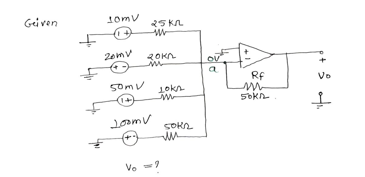
![This image depicts a summing amplifier circuit using an operational amplifier (op-amp). The circuit consists of four voltage sources, each connected to the inverting input of the op-amp through separate resistors.
### Circuit Description:
- **Voltage Sources and Resistors:**
- **10 mV** through **R1** (25 kΩ)
- **20 mV** through **R2** (20 kΩ)
- **50 mV** through **R3** (10 kΩ)
- **100 mV** through **R4** (50 kΩ)
- **Feedback Resistor:**
- The op-amp has a feedback resistor, **RF**, with a value of **50 kΩ**.
- **Op-Amp Configuration:**
- The op-amp is in an inverting configuration, meaning the input voltages are applied to the inverting terminal, and the non-inverting terminal is grounded.
### Functionality:
The summing amplifier sums the input voltages after scaling them by their respective resistances, inverting the result, and then scaling it by the feedback resistance.
### Calculation:
The output voltage \( V_o \) is calculated using the formula for a summing amplifier:
\[ V_o = -RF \left( \frac{V_1}{R1} + \frac{V_2}{R2} + \frac{V_3}{R3} + \frac{V_4}{R4} \right) \]
Substituting the given values:
\[ V_o = -50kΩ \left( \frac{10 mV}{25kΩ} + \frac{20 mV}{20kΩ} + \frac{50 mV}{10kΩ} + \frac{100 mV}{50kΩ} \right) \]
After calculation, the output voltage \( V_o \) is found to be **-120 mV**.
**Answer: \( V_o = -120 \text{ mV} \)**](/v2/_next/image?url=https%3A%2F%2Fcontent.bartleby.com%2Fqna-images%2Fquestion%2Fe36fb7f7-6381-4add-b52b-9085dfd27844%2F37072807-cc4b-4abb-a28d-d409b91a220a%2F62m0vep_processed.jpeg&w=3840&q=75)
Transcribed Image Text:This image depicts a summing amplifier circuit using an operational amplifier (op-amp). The circuit consists of four voltage sources, each connected to the inverting input of the op-amp through separate resistors.
### Circuit Description:
- **Voltage Sources and Resistors:**
- **10 mV** through **R1** (25 kΩ)
- **20 mV** through **R2** (20 kΩ)
- **50 mV** through **R3** (10 kΩ)
- **100 mV** through **R4** (50 kΩ)
- **Feedback Resistor:**
- The op-amp has a feedback resistor, **RF**, with a value of **50 kΩ**.
- **Op-Amp Configuration:**
- The op-amp is in an inverting configuration, meaning the input voltages are applied to the inverting terminal, and the non-inverting terminal is grounded.
### Functionality:
The summing amplifier sums the input voltages after scaling them by their respective resistances, inverting the result, and then scaling it by the feedback resistance.
### Calculation:
The output voltage \( V_o \) is calculated using the formula for a summing amplifier:
\[ V_o = -RF \left( \frac{V_1}{R1} + \frac{V_2}{R2} + \frac{V_3}{R3} + \frac{V_4}{R4} \right) \]
Substituting the given values:
\[ V_o = -50kΩ \left( \frac{10 mV}{25kΩ} + \frac{20 mV}{20kΩ} + \frac{50 mV}{10kΩ} + \frac{100 mV}{50kΩ} \right) \]
After calculation, the output voltage \( V_o \) is found to be **-120 mV**.
**Answer: \( V_o = -120 \text{ mV} \)**
Expert Solution
Step 1

Step by step
Solved in 2 steps with 2 images

Knowledge Booster


Learn more about
Need a deep-dive on the concept behind this application? Look no further. Learn more about this topic, electrical-engineering and related others by exploring similar questions and additional content below.Recommended textbooks for you
Introductory Circuit Analysis (13th Edition)
Electrical Engineering
ISBN:
9780133923605
Author:
Robert L. Boylestad
Publisher:
PEARSON

Delmar's Standard Textbook Of Electricity
Electrical Engineering
ISBN:
9781337900348
Author:
Stephen L. Herman
Publisher:
Cengage Learning

Programmable Logic Controllers
Electrical Engineering
ISBN:
9780073373843
Author:
Frank D. Petruzella
Publisher:
McGraw-Hill Education
Introductory Circuit Analysis (13th Edition)
Electrical Engineering
ISBN:
9780133923605
Author:
Robert L. Boylestad
Publisher:
PEARSON
Delmar's Standard Textbook Of Electricity
Electrical Engineering
ISBN:
9781337900348
Author:
Stephen L. Herman
Publisher:
Cengage Learning
Programmable Logic Controllers
Electrical Engineering
ISBN:
9780073373843
Author:
Frank D. Petruzella
Publisher:
McGraw-Hill Education

Fundamentals of Electric Circuits
Electrical Engineering
ISBN:
9780078028229
Author:
Charles K Alexander, Matthew Sadiku
Publisher:
McGraw-Hill Education

Electric Circuits. (11th Edition)
Electrical Engineering
ISBN:
9780134746968
Author:
James W. Nilsson, Susan Riedel
Publisher:
PEARSON

Engineering Electromagnetics
Electrical Engineering
ISBN:
9780078028151
Author:
Hayt, William H. (william Hart), Jr, BUCK, John A.
Publisher:
Mcgraw-hill Education,