A. What is the mesh equation that governs mesh current i1? What is i1? B. What is va? C. What is the voltage across the current source?
A. What is the mesh equation that governs mesh current i1? What is i1? B. What is va? C. What is the voltage across the current source?

Introductory Circuit Analysis (13th Edition)
13th Edition
ISBN:9780133923605
Author:Robert L. Boylestad
Publisher:Robert L. Boylestad
Chapter1: Introduction
Section: Chapter Questions
Problem 1P: Visit your local library (at school or home) and describe the extent to which it provides literature...

Related questions
Question
100%
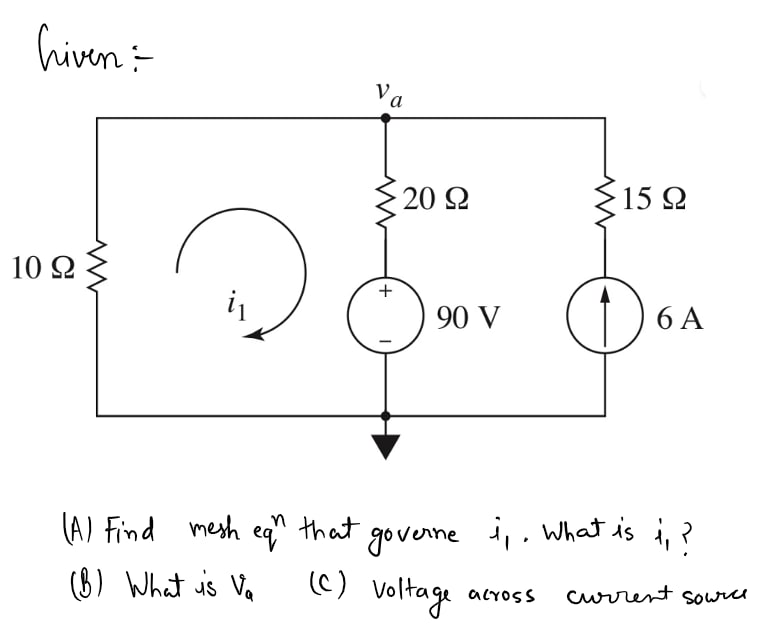
A. What is the mesh equation that governs mesh current i1? What is i1?
B. What is va?
C. What is the voltage across the current source?

Transcribed Image Text:This schematic diagram represents an electrical circuit used to study basic principles of circuit analysis, such as Ohm’s Law and Kirchhoff’s Laws.
### Components:
1. **Resistors:**
- There are three resistors in the circuit.
- \(10 \, \Omega\) resistor on the left side.
- \(20 \, \Omega\) resistor above the voltage source.
- \(15 \, \Omega\) resistor on the right side.
2. **Voltage Source:**
- A \(90 \, \text{V}\) voltage source is positioned below the \(20 \, \Omega\) resistor, indicating that it supplies energy to the circuit, with the positive terminal on the upper side.
3. **Current Source:**
- A \(6 \, \text{A}\) current source is on the far right, pointing upwards, indicating the direction of current flow through this part of the circuit.
4. **Current Loop:**
- A loop is drawn in the diagram with an arrow and labeled \(i_1\), indicating the direction of assumed current flow in the loop, which is counterclockwise.
5. **Nodes:**
- Two nodes are shown in the diagram:
- The top node is labeled \(v_a\), marking it as a point of interest for potential difference.
### Circuit Analysis:
The circuit design allows for the application of Kirchhoff's Voltage Law (KVL) around the closed loop, as well as Kirchhoff's Current Law (KCL) at the nodes. This can help in calculating unknown currents or voltages in the circuit.
This schematic serves as a basis for understanding the flow of electricity in closed circuits, the impact of resistive loads, and the contribution of active sources of voltage and current.
Expert Solution
Step 1

Step by step
Solved in 2 steps with 2 images

Knowledge Booster


Learn more about
Need a deep-dive on the concept behind this application? Look no further. Learn more about this topic, electrical-engineering and related others by exploring similar questions and additional content below.Recommended textbooks for you
Introductory Circuit Analysis (13th Edition)
Electrical Engineering
ISBN:
9780133923605
Author:
Robert L. Boylestad
Publisher:
PEARSON

Delmar's Standard Textbook Of Electricity
Electrical Engineering
ISBN:
9781337900348
Author:
Stephen L. Herman
Publisher:
Cengage Learning

Programmable Logic Controllers
Electrical Engineering
ISBN:
9780073373843
Author:
Frank D. Petruzella
Publisher:
McGraw-Hill Education
Introductory Circuit Analysis (13th Edition)
Electrical Engineering
ISBN:
9780133923605
Author:
Robert L. Boylestad
Publisher:
PEARSON
Delmar's Standard Textbook Of Electricity
Electrical Engineering
ISBN:
9781337900348
Author:
Stephen L. Herman
Publisher:
Cengage Learning
Programmable Logic Controllers
Electrical Engineering
ISBN:
9780073373843
Author:
Frank D. Petruzella
Publisher:
McGraw-Hill Education

Fundamentals of Electric Circuits
Electrical Engineering
ISBN:
9780078028229
Author:
Charles K Alexander, Matthew Sadiku
Publisher:
McGraw-Hill Education

Electric Circuits. (11th Edition)
Electrical Engineering
ISBN:
9780134746968
Author:
James W. Nilsson, Susan Riedel
Publisher:
PEARSON

Engineering Electromagnetics
Electrical Engineering
ISBN:
9780078028151
Author:
Hayt, William H. (william Hart), Jr, BUCK, John A.
Publisher:
Mcgraw-hill Education,