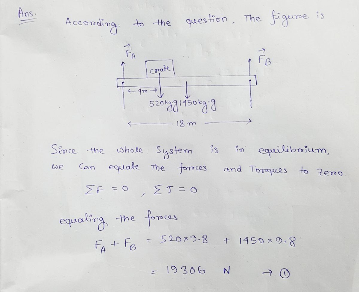
A uniform 1450 kg beam that is 18 m long is balanced on two vertical support beams at either end of the beam (see figure 9-8). A crate which weighs 520 kg is positioned 4.0 m from the first support beam. Calculate the force on each of the vertical support beams.
A uniform 1450 kg beam that is 18 m long is balanced on two vertical support beams at either end of the beam (see figure 9-8). A crate which weighs 520 kg is positioned 4.0 m from the first support beam. Calculate the force on each of the vertical support beams.
Related questions
Question
100%

Transcribed Image Text:**Figure 9-8 Description for Educational Website**
This diagram illustrates a mechanical scenario where a 1500-kg beam supports a 15,000-kg machine. Below are the key elements in the figure:
- **Beam Support Forces:** The beam is supported at two points, labeled as \( \vec{F}_A \) and \( \vec{F}_B \), representing upward support forces at the left and right ends of the beam, respectively.
- **Machine Load:** The machine exerts a downward force on the beam, depicted as \( (15,000 \, \text{kg})\vec{g} \), where \( \vec{g} \) represents gravitational acceleration. This force is applied at the center of gravity (CG) of the machine.
- **Beam Load:** The beam itself also has a weight, shown as \( (1500 \, \text{kg})\vec{g} \), acting downwards, again due to gravity.
- **Distances:** The key distances are labeled to indicate the positions of the forces:
- The distance from the left end (point \( P \)) of the beam to the center of gravity of the machine is 10.0 meters.
- The center of gravity of the beam is located 5.0 meters from each support point.
This setup is an example of static equilibrium, where the sum of the forces and moments around any point is zero, ensuring the beam is balanced. This analysis is critical in engineering to ensure structural stability.

Transcribed Image Text:A uniform 1450 kg beam that is 18 m long is balanced on two vertical support beams at either end of the beam (see figure 9-8). A crate which weighs 520 kg is positioned 4.0 m from the first support beam. Calculate the force on each of the vertical support beams.
Expert Solution
Step 1

Step by step
Solved in 2 steps with 2 images
