a) RTotal =_ b) |Total = 201 c) ₁ = Figure (2) 3) The circuit in Figure (2) has values of, V = 40 Volt, R₁ = 40 S2, R₂ = 80 2 and R3 = 80 N. Calculate the following values for the circuit. , 1₂ =_ R₁ Verify, 11 + 12 + 13 = | Total 13=_ R2 V =40 Volt, R₁ = 40 2, R₂ = 60 N, R3 = 120 . R3 4) For the circuit in Figure (2), the voltage and the resistor values are changed as follows: Calculate RTotal and Total is equal to the sum of 11, 12, 13.
a) RTotal =_ b) |Total = 201 c) ₁ = Figure (2) 3) The circuit in Figure (2) has values of, V = 40 Volt, R₁ = 40 S2, R₂ = 80 2 and R3 = 80 N. Calculate the following values for the circuit. , 1₂ =_ R₁ Verify, 11 + 12 + 13 = | Total 13=_ R2 V =40 Volt, R₁ = 40 2, R₂ = 60 N, R3 = 120 . R3 4) For the circuit in Figure (2), the voltage and the resistor values are changed as follows: Calculate RTotal and Total is equal to the sum of 11, 12, 13.

Introductory Circuit Analysis (13th Edition)
13th Edition
ISBN:9780133923605
Author:Robert L. Boylestad
Publisher:Robert L. Boylestad
Chapter1: Introduction
Section: Chapter Questions
Problem 1P: Visit your local library (at school or home) and describe the extent to which it provides literature...

Related questions

Question
![### Educational Content: Circuit Analysis
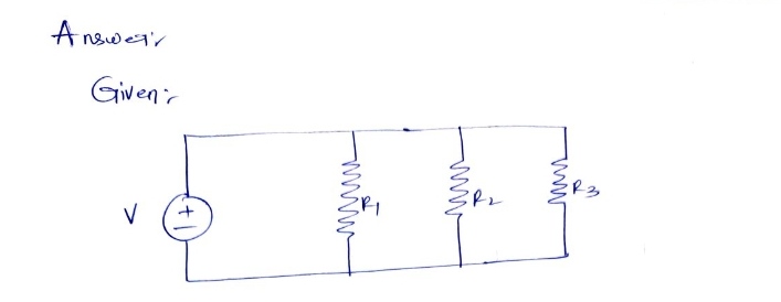
#### Diagram Explanation
The diagram shows a mixed-resistor circuit configuration with a voltage source \( V \) and three resistors \( R_1, R_2, R_3 \). The resistors \( R_2 \) and \( R_3 \) are in parallel, and their combination is in series with \( R_1 \).
#### Circuit Values and Calculations
1. **Given Values in Figure (2):**
- \( V = 40 \) Volt
- \( R_1 = 40 \, \Omega \)
- \( R_2 = 80 \, \Omega \)
- \( R_3 = 80 \, \Omega \)
2. **Tasks: Calculate the following values for the circuit.**
a) \( R_{\text{Total}} \)
\[ R_{\text{Total}} = \text{(Series + Parallel Calculation)} \]
b) \( I_{\text{Total}} \)
\[ I_{\text{Total}} = \frac{V}{R_{\text{Total}}} \]
c) Current through each resistor:
\[ I_1 = \, \, \]
\[ I_2 = \, \, \]
\[ I_3 = \, \, \]
**Verification:**
\[ I_1 + I_2 + I_3 = I_{\text{Total}} \]
3. **Modified Circuit in Figure (2):**
- \( V = 40 \) Volt
- \( R_1 = 40 \, \Omega \)
- \( R_2 = 60 \, \Omega \)
- \( R_3 = 120 \, \Omega \)
4. **Tasks: Calculate \( R_{\text{Total}} \) and verify \( I_{\text{Total}} \) is equal to the sum of \( I_1, I_2, I_3 \).**
This exercise provides practice in calculating total resistance for series and parallel circuits, as well as verifying current distribution and total current using Ohm’s Law.](/v2/_next/image?url=https%3A%2F%2Fcontent.bartleby.com%2Fqna-images%2Fquestion%2F0ab994c8-cff9-4fe5-97d8-93d0776b49d9%2F0fed6936-fe2e-46cb-a364-a5f91540eefb%2Fbagq8ek_processed.png&w=3840&q=75)
Transcribed Image Text:### Educational Content: Circuit Analysis
#### Diagram Explanation
The diagram shows a mixed-resistor circuit configuration with a voltage source \( V \) and three resistors \( R_1, R_2, R_3 \). The resistors \( R_2 \) and \( R_3 \) are in parallel, and their combination is in series with \( R_1 \).
#### Circuit Values and Calculations
1. **Given Values in Figure (2):**
- \( V = 40 \) Volt
- \( R_1 = 40 \, \Omega \)
- \( R_2 = 80 \, \Omega \)
- \( R_3 = 80 \, \Omega \)
2. **Tasks: Calculate the following values for the circuit.**
a) \( R_{\text{Total}} \)
\[ R_{\text{Total}} = \text{(Series + Parallel Calculation)} \]
b) \( I_{\text{Total}} \)
\[ I_{\text{Total}} = \frac{V}{R_{\text{Total}}} \]
c) Current through each resistor:
\[ I_1 = \, \, \]
\[ I_2 = \, \, \]
\[ I_3 = \, \, \]
**Verification:**
\[ I_1 + I_2 + I_3 = I_{\text{Total}} \]
3. **Modified Circuit in Figure (2):**
- \( V = 40 \) Volt
- \( R_1 = 40 \, \Omega \)
- \( R_2 = 60 \, \Omega \)
- \( R_3 = 120 \, \Omega \)
4. **Tasks: Calculate \( R_{\text{Total}} \) and verify \( I_{\text{Total}} \) is equal to the sum of \( I_1, I_2, I_3 \).**
This exercise provides practice in calculating total resistance for series and parallel circuits, as well as verifying current distribution and total current using Ohm’s Law.
Expert Solution
Step 1

Step by step
Solved in 3 steps with 3 images

Knowledge Booster


Learn more about
Need a deep-dive on the concept behind this application? Look no further. Learn more about this topic, electrical-engineering and related others by exploring similar questions and additional content below.Recommended textbooks for you
Introductory Circuit Analysis (13th Edition)
Electrical Engineering
ISBN:
9780133923605
Author:
Robert L. Boylestad
Publisher:
PEARSON

Delmar's Standard Textbook Of Electricity
Electrical Engineering
ISBN:
9781337900348
Author:
Stephen L. Herman
Publisher:
Cengage Learning

Programmable Logic Controllers
Electrical Engineering
ISBN:
9780073373843
Author:
Frank D. Petruzella
Publisher:
McGraw-Hill Education
Introductory Circuit Analysis (13th Edition)
Electrical Engineering
ISBN:
9780133923605
Author:
Robert L. Boylestad
Publisher:
PEARSON
Delmar's Standard Textbook Of Electricity
Electrical Engineering
ISBN:
9781337900348
Author:
Stephen L. Herman
Publisher:
Cengage Learning
Programmable Logic Controllers
Electrical Engineering
ISBN:
9780073373843
Author:
Frank D. Petruzella
Publisher:
McGraw-Hill Education

Fundamentals of Electric Circuits
Electrical Engineering
ISBN:
9780078028229
Author:
Charles K Alexander, Matthew Sadiku
Publisher:
McGraw-Hill Education

Electric Circuits. (11th Edition)
Electrical Engineering
ISBN:
9780134746968
Author:
James W. Nilsson, Susan Riedel
Publisher:
PEARSON

Engineering Electromagnetics
Electrical Engineering
ISBN:
9780078028151
Author:
Hayt, William H. (william Hart), Jr, BUCK, John A.
Publisher:
Mcgraw-hill Education,