a) oscillates with a period of 8.000 ms? b) At what angle should the knob be set so that the circuit What voltage battery do I need to charge up the capacitor to an initial charge of 87.60 µC? (assume the period is set to 8.000 ms) What is the maximum current in this LC Circuit? c) (assume the initial charge is 87.60 µC)
a) oscillates with a period of 8.000 ms? b) At what angle should the knob be set so that the circuit What voltage battery do I need to charge up the capacitor to an initial charge of 87.60 µC? (assume the period is set to 8.000 ms) What is the maximum current in this LC Circuit? c) (assume the initial charge is 87.60 µC)

Introductory Circuit Analysis (13th Edition)
13th Edition
ISBN:9780133923605
Author:Robert L. Boylestad
Publisher:Robert L. Boylestad
Chapter1: Introduction
Section: Chapter Questions
Problem 1P: Visit your local library (at school or home) and describe the extent to which it provides literature...

Related questions

Question
100%

Transcribed Image Text:2) An LC circuit is made by attaching a 0.2221 H inductor is connected across a
variable capacitor whose capacitance can be varied by turning a knob.
a) . At what angle should the knob be set so that the circuit
ocillates with a period of 8.000 ms?
SuF
OµF
- 10µF
b)
What voltage battery do I need to charge up the capacitor to an
initial charge of 87.60 µC? (assume the period is set to 8.000 ms)
Сарасiance
c)
What is the maximum current in this LC Circuit?
(all numbers 4 sig figs)
(assume the initial charge is 87.60 µC)
Expert Solution
Step 1
a)
The LC circuit’s frequency can be represented as,
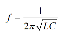
Here, L and C represent the inductance and capacitance, respectively.
Also,
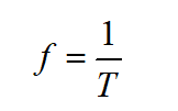
Here, T is the time period.
Thus,
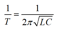
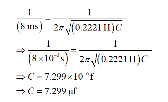
Substitute the relevant values.
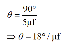
Now, the knob makes an angle of 900 for 5μf capacitance.
Thus, for 1μf, the knob’s angle can be found as,
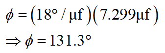
Thus, for 7.299μf, the knob’s angle is,
Substitute the relevant values.
Step 2
b)
In part (a), the capacitor required to have a time period of 8 ms is found to be 7.299μf.
Now, the charge in a capacitor can be represented as,
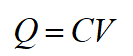
Here, V represents the capacitor’s voltage.
Substitute the relevant values.
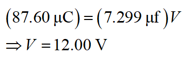
Thus, the capacitor’s voltage is about 12.00 V.

Step by step
Solved in 3 steps with 12 images

Knowledge Booster


Learn more about
Need a deep-dive on the concept behind this application? Look no further. Learn more about this topic, electrical-engineering and related others by exploring similar questions and additional content below.Recommended textbooks for you
Introductory Circuit Analysis (13th Edition)
Electrical Engineering
ISBN:
9780133923605
Author:
Robert L. Boylestad
Publisher:
PEARSON

Delmar's Standard Textbook Of Electricity
Electrical Engineering
ISBN:
9781337900348
Author:
Stephen L. Herman
Publisher:
Cengage Learning

Programmable Logic Controllers
Electrical Engineering
ISBN:
9780073373843
Author:
Frank D. Petruzella
Publisher:
McGraw-Hill Education
Introductory Circuit Analysis (13th Edition)
Electrical Engineering
ISBN:
9780133923605
Author:
Robert L. Boylestad
Publisher:
PEARSON
Delmar's Standard Textbook Of Electricity
Electrical Engineering
ISBN:
9781337900348
Author:
Stephen L. Herman
Publisher:
Cengage Learning
Programmable Logic Controllers
Electrical Engineering
ISBN:
9780073373843
Author:
Frank D. Petruzella
Publisher:
McGraw-Hill Education

Fundamentals of Electric Circuits
Electrical Engineering
ISBN:
9780078028229
Author:
Charles K Alexander, Matthew Sadiku
Publisher:
McGraw-Hill Education

Electric Circuits. (11th Edition)
Electrical Engineering
ISBN:
9780134746968
Author:
James W. Nilsson, Susan Riedel
Publisher:
PEARSON

Engineering Electromagnetics
Electrical Engineering
ISBN:
9780078028151
Author:
Hayt, William H. (william Hart), Jr, BUCK, John A.
Publisher:
Mcgraw-hill Education,