'7 For t> 0, determine for what value of t i = 2.5 A in the circuit of Figure P5.77 if the circuit is in steady state at t = 0-. 2Ω ww 40 V :20 3Ω ww
Q: 9 At t 0.
A: Given circuit is – Given values are –
Q: 3 Assume that the circuit shown in Figure P5.73 is underdamped and that the circuit initially has no…
A: The circuit is under-damped circuit and has no initial energy stored. The circuit diagram is shown…
Q: Consider the phasors shown in Figure P5.22. The frequency of each signal is f=200 Hz. Write a…
A: Frequency is given f = 200 Hz. Angular frequency is given by,
Q: 4 Determine the current through the capacitor just before and just after the switch is closed in…
A: Before the switch is closed the steady-state condition can be assumed, this means the capacitor is…
Q: 6 Find the maximum value of v(t) for t > 0 in the circuit of Figure P5.76 if the circuit is in…
A: It is known that the inductor behaves as the short circuit and the capacitor behaves as an open…
Q: The circuit shown in _below figure consists of ideal capacitors, inductors, resistors and current…
A:
Q: P5.6. A sinusoidal voltage has a peak value of 15 V, has a frequency of 125 Hz, and crosses zero…
A: Sinusoidal voltage A…
Q: Consider the situation shown in Figure P5.85. A 1000-V-rms source delivers power to a load. The load…
A: (a) When capacitor is not connected, to calculate the RMS value of current we will use the actual…
Q: 41 For the circuit shown in Figure P5.41, assume that switch Sj is always open and that switch Sz…
A: Hello. Since your question has multiple sub-parts, we will solve first three sub-parts for you. If…
Q: For t > 0, determine for what value of t v = 7.5 Vin the circuit of Figure P5.79 if the circuit…
A: Draw the schematic diagram of the circuit just before the switch is opened. First, calculate the…
Q: 2 At t < 0, the circuit shown in Figure P5.22 is at steady state. The switch is changed as shown at…
A:
Q: Assume the circuit of Figure P5.72 initially storesno energy. Switch S1 is open and S2 is closed.…
A: Since the capacitor and the inductor are not connected to the voltage source before t < 5 sec,…
Q: For the circuit of Figure P5.70, determine if it isunderdamped or overdamped. Find also the…
A: The given circuit is the series RLC circuit. The expression of the damping coefficient of the…
Q: Assume that the circuit shown in Figure P5.73 isunderdamped and that the circuit initially has…
A: The steady-state value of the voltage is 50 V. The value reached in overshoot is 70 V. The peak time…
Q: Write the differential equation for t > 0 for thecircuit of Figure P5.21.
A: Consider the circuit after the switch is opened. Now, apply Ohm’s law and calculate the current…
Q: An inductor is one of important device in electrical circuits. To study response of it in pure form,…
A: Current through the inductor can be easily calculated if the values of the voltage and the inductive…
Q: '8 For t> 0, determine for what value of t i = 6 A in the circuit of Figure P5.78 if the circuit is…
A: Draw the schematic diagram of the circuit just before the switch is shifted.
Q: 1 In the circuit shown in Figure P5.61: Vsi = 15 V Rsi = 130 2 Vsz = 9 V Rs2 = 290 2 %3D R = 1.1 k2…
A: From the circuit diagram, the switch is opened and the circuit is in DC steady-state conditions as t…
Q: o Steady-state conditions exist in the circuit shown in Figure P5.27 for t 0.
A: When the switch is closed, then for calculating the time constant replace the source with the short…
Q: 4 If the switch in the circuit shown in Figure P5.64 is closed at t = 0 and Vs = 12 V C = 130 µF R =…
A: It is known that the inductor behaves as a short circuit and the capacitor behaves as an open…
Q: For the circuit of Figure P5.52, assume that thecircuit is at steady state for t < 0. Find the…
A: Draw the given circuit for t>0.
Q: Write the differential equation for t > 0 for thecircuit of Figure P5.29.
A: When the circuit is not shifted, the inductor behaves as short-circuit. The current through the…
Q: Plot the graph between P vs Va in Dc shunt excitation motor
A: In dc shunt motor speed is nearly constant. The relation between power and voltage is non linear.…
Q: P5.17. Find the rms value of the voltage waveform shown in Figure P5.17 D. V(1) T= 2 Figure P5.17
A:
Q: t=0 Rs1 Rs2 LE R Vsi R2 Vs2 Figure P5.61 2 In the circuit shown in Figure P5.61 Vsi = 12 V Rsi = 50…
A: As it is known that the capacitor behaves as an open circuit and the inductor behaves as the short…
Q: 7 In the circuit shown in Figure P5.67, assume that DC steady-state conditions exist for t < 0.…
A: It is given that the switch is closed and the circuit is under DC steady-state condition for t = 0-.…
Q: 4 We use an analogy between electric circuits and thermal conduction to analyze the behavior of a…
A: Write the expression for the charging in the capacitor, Since there are the current source and a…
Q: 8 In the circuit shown in Figure P5.67, Vsi = 12 V Rsı = 50 2 Vsz = 12 V Rsz = 50 2 R = 2.2 k2 R2 =…
A: From the circuit diagram, the switch is opened and the circuit is in DC steady-state conditions as t…
Q: 5 If the switch in the circuit shown in Figure P5.65 is closed at t = 0 and Vs = 12 V R = 31 k2 L=…
A: The circuit for which the current across the inductor in the steady stet and the voltage across the…
Q: The inductor L in the circuit shown in Figure P5.36is the coil of a relay. When the current through…
A: For t < 0, The current through the inductor is zero. As the inductor does not allow the sudden…
Q: Assume that S1 and S2 close at t = 0 in FigureP5.41.a. Find the capacitor voltage vC(t) at t = 0+.…
A: Since we only answer up to 3 sub-parts, we’ll answer the first 3. Please resubmit the question and…
Q: For the circuit below with input voltage V1, a step function of magnitude 25 volts at time t=0, find…
A: For the given series RLC circuit, R1=555 Ω, L1=250 mH, C1=3.3 μF; the input voltage is a step…
Q: Find I in the circuit in Fig. P5.32 12 V 4 kN 4 kN 6 kN 6 kN 6 mA Figure P5.32
A: The solution can be given for kcl and kvl
Q: 3 If the switch in the circuit shown in Figure P5.63 is closed at t = 0 and Vs = 170 V Rs = 7 k2 R =…
A: The circuit diagram is shown below: During the steady-state, the capacitor will act as an open…
Q: 5.56 The circuit of Figure P5.56 is used as a variable delay in a burglar alarm. The alarm is a…
A: Draw the circuit just after the switch is closed.
Q: Write the differential equation for t > 0 for thecircuit of Figure P5.32.
A: The circuit diagram is shown below: At t=0, the switch of the given circuit is moved from R1 to R2.…
Q: The capacitor behaves as an open circuit to a DC source. Why? How does the inductor behave to a DC…
A: explaination
Q: 6 At t< 0, the circuit shown in Figure P5.66 is at steady state, and the voltage across the…
A: For t < 0, the inductor is short-circuited at the steady state. Find the current through the…
Q: For the circuit below with input voltage V1, a step function of magnitude 15 volts at time t=0, find…
A: A circuit's transient response is a short-term change in how it operates as a result of an external…
Q: 7 Steady-state conditions exist in the circuit shown in Figure P5.27 at t < 0. The switch is closed…
A: Before the switch is closed, the voltage across the capacitor is, As the capacitor does not allow…
Q: Write the differential equation for t > 0 for thecircuit of Figure P5.23.
A: Let ic be the current through the capacitor, i2 be the current through resistor R2, and i1 be the…
Q: Determine the initial and final conditions for thecircuit of Figure P5.23.
A: Draw the circuit diagram just before the switch is closed.
Q: Write the differential equation for t > 0 for thecircuit of Figure P5.52.
A: When the switch is closed for t > 0, Draw the equivalent circuit.
Q: 37. The Thévenin equivalent of a two-terminal quency is f = 60 Hz. We wish to connect a network is…
A: The solution can be achieved as follows.
Q: The switch in the circuit of Figure P5.58 opens att = 0. It closes at t = 10 seconds.a. What is the…
A: The circuit diagram is, The switch in the circuit opens at t = 0 s and closes at t = 10 s. a). The…
Q: i) in the design problem system specifications are usually givicn terms of: (a) Transient and steady…
A: Solve the problem
Q: 6. Reduce the block diagram shown in Figure P5.6 to a single block, T(s) = C(s)/R(s). [Section: 52]…
A: The reduced diagram is drawn below, From the diagram, the result of the summation is, Now, the…
Q: 8 For t > 0, the circuit shown in Figure P5.22 is at steady state. The switch is changed as shown at…
A: The circuit diagram is,
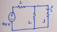
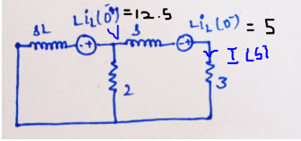
At the steady-state, the inductors act as the short circuit and the circuit becomes completely resistive as shown in the figure given below.
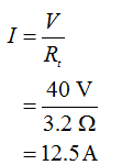
The current drawn for the source is given by,
The current drawn from the source.
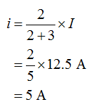
The current I shown in the figure is given by,
When the position of the switch is changed, take the Laplace transform of the circuit.
Keep in mind that after closing the switch the inductor will behave like the voltage source so mention the current source in the Laplace domain.
Step by step
Solved in 6 steps with 10 images
- Solve for the node voltages shown in Figure P5.53. 10/0 (+ 10 2 +j20 2 15 n 1 Figure P5.53 000What impedance vector - j25 represents:A. A pure resistance. C. A pure capacitance.B. A pure inductance. D. An inductance combined with a resistance.Q5)-a)For this figure shown below the phase relationship between the sinusoidal waveform Of this set. -10sin(wt+80) V=15sin (wt+40) Q5)-b) for this circuit find the max energy if XL=100 Vm-300v,L=0.3H V= Vm Sinwt
- Let's say you measure t1/2 to be 0.037 seconds and the resistance in the circuit is 68 Ohms. Then what is the capacitance in micro Farads? Answer in micro Farads.Shown in the figure below is an "RL" circuit drive by an AC power source. The AC power source has an RMS voltage of Vps (RMS) = 9.84 Volts and is running at a frequency of f = 8.585e+04 Hz. The resistor has a resistance of R = 2170 and the inductor has an inductance of L = 3.54e-03 Henries. Vps R ww Write the FORMULA for the total impedance of the circuit Ztot = Determine the numerical value of Ztot = 2890.5 Determine the numerical value of $z= = 41 Determine the current through the circuit: • I(PEAK) = 4.81E-3 • I(RMS) = 3.404E-3 Determine the voltage across the resistor: • VR(PEAK) = 7.387 • VR(RMS) = 5.22 ✔✔ Amps ✔Amps Write the FORMULA for the phase of the total impedance of the circuit z... = | tan-1 2701 R x Volts X Volts Determine the voltage across the inductor: • VL(PEAK) = 9.184 • VL(RMS) = 6.49 ✔ Volts Volts L R²+ WL- ✔ degrees 2 If a second circuit were connected in parallel with the inductor, this circuit would be considered as: O a low-pass filter O a capacitive switcher…What impedance vector (0- j15) Ohms represents:A. A pure resistance. C. A pure capacitance.B. A pure inductance. D. An inductance combined with a capacitance.
- *P5.81. Two loads, A and B, are connected in parallel across a 1-kV-rms 60-Hz line, as shown in Figure P5.81. Load A consumes has an apparent power of 15 and contine es tor: wind wer and a 90 percent lagging power factor. Load B an Find the 1 kV rms 60 Hz 80 percent lagging power factor. power, reactive power, and apparent power delivered by the source. What is the power factor seen by the source? Iline A Figure P5.81 10 kW with B IBThe ripple factor for pure dc is Answer:P5.90. a. Find the Thévento and Norton equivalent circuits for the circuit shown in Figure P5.90. b. Find the maximum power that this circuit can deliver to a load if the load can have any complex impedance. c. Repeat if the load must be purely resistive. 100/45° 10 Ω www enpea gineering Pr +j5 n Figure P5.90 15/0°
- Consider the circuit shown in Figure P5.49. Find the phasors Is, V, IR, IL and IC. Compare the peak value of iL(t) with the peak value of is(t). Do you find the answer surprising? Explain.A capacitor "C", an inductor "L" and a switch "S" are connected in series. When the switch is open, the plate to the left of the capacitor has charge "Qo". The switch is closed the load and current vary sinusoidally with time. Represent graphically the load "Qo" and the intensity of current "I" as a function of time "t", and explain why the current leads the load by a phase difference of 90°.A resistor & a capacitor are connected in series across 230V, ac supply. The current taken by the circuit is 4 A for 50 Hz frequency. The current is reduced to 2 A, when the frequency of supply is decreased to 40 Hz. Determine the value of resistor & the capacitor.