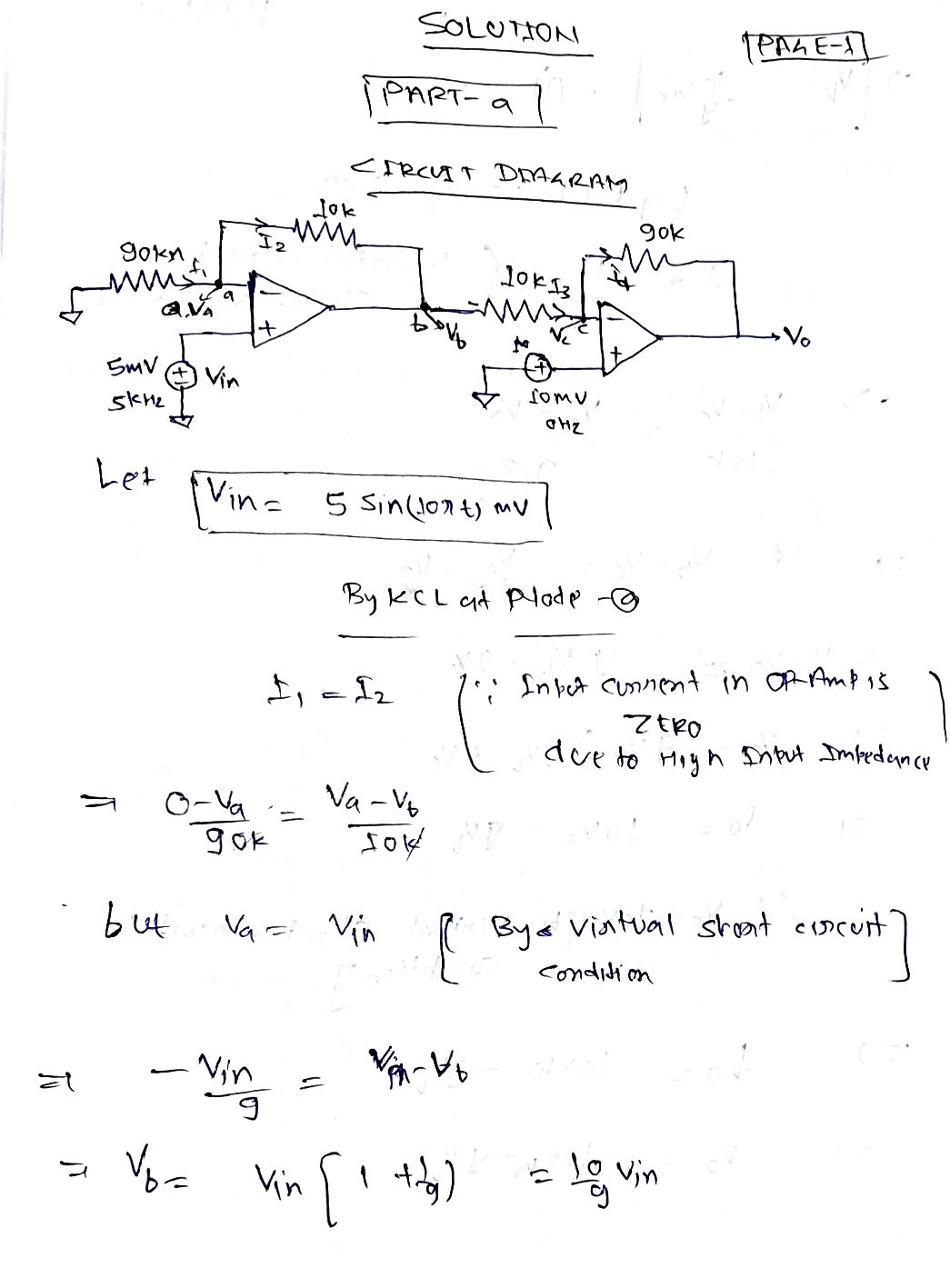
5. Sketch the output voltage as a function of time in the circuits below. 90k www lok 100H 5mV @ 5kHz SOK IOK un 10mV@ 10K ww OHL 90k www. 150k w Vo №o
5. Sketch the output voltage as a function of time in the circuits below. 90k www lok 100H 5mV @ 5kHz SOK IOK un 10mV@ 10K ww OHL 90k www. 150k w Vo №o

Introductory Circuit Analysis (13th Edition)
13th Edition
ISBN:9780133923605
Author:Robert L. Boylestad
Publisher:Robert L. Boylestad
Chapter1: Introduction
Section: Chapter Questions
Problem 1P: Visit your local library (at school or home) and describe the extent to which it provides literature...

Related questions

Question
5 please all parts will give like!!!

Transcribed Image Text:**Op Amps Handout #2**
**1. Inverting Amplifier Design and Analysis**
- **a. Design Task:** Configure an inverting amplifier with a gain of 25 using practical components.
- **b. Signal Input Analysis:** If this amplifier connects to a signal generator producing a 20mV peak-to-peak sine wave at 1kHz, determine the ideal output voltage.
- **c. Source Resistance Impact:** Consider a signal generator with a 50 ohm source resistance. Assess how this influences the output voltage in your design.
- **Questions:**
1. What frequency can your amplifier accurately reproduce?
2. What is the maximum input voltage your amplifier can suitably reproduce without distortion?
**2. Non-Inverting Amplifier Design and Improvement**
- **Task:** Create a non-inverting amplifier with a gain of 100.
- **Advantages:** Discuss the benefits of this design over the inverting configuration.
- **Zero Input Voltage Analysis:** Determine the maximum range of output voltage using a 741C op-amp at temperatures between 0 to 70°C.
- **Square Wave Response:** For a 2kHz square wave with a 100mVp-p amplitude, sketch the expected output waveform.
- **Impact of Source Resistance:** Analyze how a 100kohm source resistance affects the output in the previous scenario.
**3. Instrumentation Amplifier Evaluation**
- **Precision Design:** Design a three op-amp instrumentation amplifier for a gain of 200.
- **CMRR Consideration:** Calculate the common-mode rejection ratio (CMRR) if there's a 1% error in resistance ratio.
- **Error Signal Calculation:** Calculate the output signal for a 60Hz common-mode signal with a 5V amplitude.
**4. Summing Circuit Design**
- **Objective:** Develop an op-amp circuit to resolve the voltage equation: V0=3V1+2V2+5V3.
- **Implementation:** Use a reference voltage of 1.5V and show two design approaches when Vin is ±500mV.
- **Error Correction:** Identify potential errors leading to output distortion at ±13.5V.
**5. Sketching Output Voltages**
- **Task:** Illustrate the output voltage as a function of time for the following scenarios:
- **a. Circuit Analysis 1:**
Expert Solution
Step 1

Step by step
Solved in 6 steps with 6 images

Knowledge Booster


Learn more about
Need a deep-dive on the concept behind this application? Look no further. Learn more about this topic, electrical-engineering and related others by exploring similar questions and additional content below.Recommended textbooks for you
Introductory Circuit Analysis (13th Edition)
Electrical Engineering
ISBN:
9780133923605
Author:
Robert L. Boylestad
Publisher:
PEARSON

Delmar's Standard Textbook Of Electricity
Electrical Engineering
ISBN:
9781337900348
Author:
Stephen L. Herman
Publisher:
Cengage Learning

Programmable Logic Controllers
Electrical Engineering
ISBN:
9780073373843
Author:
Frank D. Petruzella
Publisher:
McGraw-Hill Education
Introductory Circuit Analysis (13th Edition)
Electrical Engineering
ISBN:
9780133923605
Author:
Robert L. Boylestad
Publisher:
PEARSON
Delmar's Standard Textbook Of Electricity
Electrical Engineering
ISBN:
9781337900348
Author:
Stephen L. Herman
Publisher:
Cengage Learning
Programmable Logic Controllers
Electrical Engineering
ISBN:
9780073373843
Author:
Frank D. Petruzella
Publisher:
McGraw-Hill Education

Fundamentals of Electric Circuits
Electrical Engineering
ISBN:
9780078028229
Author:
Charles K Alexander, Matthew Sadiku
Publisher:
McGraw-Hill Education

Electric Circuits. (11th Edition)
Electrical Engineering
ISBN:
9780134746968
Author:
James W. Nilsson, Susan Riedel
Publisher:
PEARSON

Engineering Electromagnetics
Electrical Engineering
ISBN:
9780078028151
Author:
Hayt, William H. (william Hart), Jr, BUCK, John A.
Publisher:
Mcgraw-hill Education,