4 m 250 N 250 N 500 N 3m A 2m a O 19 A 335 N 559 N 500 N 250 N 250 N 250 N (b) e e 335 N 500 N 559 N 500 N
4 m 250 N 250 N 500 N 3m A 2m a O 19 A 335 N 559 N 500 N 250 N 250 N 250 N (b) e e 335 N 500 N 559 N 500 N
Elements Of Electromagnetics
7th Edition
ISBN:9780190698614
Author:Sadiku, Matthew N. O.
Publisher:Sadiku, Matthew N. O.
ChapterMA: Math Assessment
Section: Chapter Questions
Problem 1.1MA
Related questions
Question
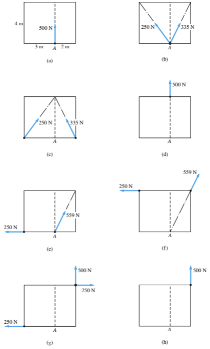
which if any of these possible pictures, are equivalent to A

Transcribed Image Text:### Understanding Force Equilibrium and Vector Components
This set of diagrams illustrates different scenarios in which forces act on a body at point \( A \) to maintain equilibrium. The diagrams demonstrate how forces can be broken down into components and combined in various configurations to achieve equilibrium.
#### Diagram Descriptions:
- **Diagram (a):**
- A rectangle with a vertical line of symmetry.
- A single force of 500 N is acting vertically upwards at point \( A \), located 3 meters from the left and 2 meters from the right.
- **Diagram (b):**
- Two forces are acting upward diagonally towards point \( A \).
- Left force: 250 N directed into angle.
- Right force: 335 N directed into angle.
- **Diagram (c):**
- Similar structure to (b).
- Force vectors are each labeled as 250 N and 335 N, arranged symmetrically.
- **Diagram (d):**
- A single 500 N force is applied directly upwards at point \( A \), indicating no horizontal components.
- **Diagram (e):**
- Two forces: a 250 N horizontal force pushing to the left, and a 559 N force pointing upwards at an angle to the right.
- **Diagram (f):**
- Similar structure with the 250 N horizontal force to the left.
- A 559 N force oriented upwards at an angle from the vertical line to point \( A \).
- **Diagram (g):**
- A 250 N horizontal force is present along the bottom, pointing to the right.
- A vertical 500 N force is applied at \( A \), while a horizontal force (250 N) acts to the right.
- **Diagram (h):**
- A vertical force of 500 N is acting upwards at \( A \).
- It is symmetric with no horizontal components.
### Explanation:
These diagrams are frequently used in physics and engineering to portray the principles of static equilibrium, where the sum of forces and moments acting on the body are zero.
- **Vector Components:**
- Forces are sometimes broken down into components (horizontal and vertical) to simplify calculations related to equilibrium.
- **Equilibrium Conditions:**
- For a body to be in equilibrium, the net force and the net moment about any point should be zero.
- **Resultant Forces:**
- In diagrams b,
Expert Solution
Step 1: Given data
which of these possible pictures, are equivalent to fig (a).

Step by step
Solved in 9 steps with 8 images

Knowledge Booster
Learn more about
Need a deep-dive on the concept behind this application? Look no further. Learn more about this topic, mechanical-engineering and related others by exploring similar questions and additional content below.Recommended textbooks for you

Elements Of Electromagnetics
Mechanical Engineering
ISBN:
9780190698614
Author:
Sadiku, Matthew N. O.
Publisher:
Oxford University Press

Mechanics of Materials (10th Edition)
Mechanical Engineering
ISBN:
9780134319650
Author:
Russell C. Hibbeler
Publisher:
PEARSON

Thermodynamics: An Engineering Approach
Mechanical Engineering
ISBN:
9781259822674
Author:
Yunus A. Cengel Dr., Michael A. Boles
Publisher:
McGraw-Hill Education

Elements Of Electromagnetics
Mechanical Engineering
ISBN:
9780190698614
Author:
Sadiku, Matthew N. O.
Publisher:
Oxford University Press

Mechanics of Materials (10th Edition)
Mechanical Engineering
ISBN:
9780134319650
Author:
Russell C. Hibbeler
Publisher:
PEARSON

Thermodynamics: An Engineering Approach
Mechanical Engineering
ISBN:
9781259822674
Author:
Yunus A. Cengel Dr., Michael A. Boles
Publisher:
McGraw-Hill Education

Control Systems Engineering
Mechanical Engineering
ISBN:
9781118170519
Author:
Norman S. Nise
Publisher:
WILEY

Mechanics of Materials (MindTap Course List)
Mechanical Engineering
ISBN:
9781337093347
Author:
Barry J. Goodno, James M. Gere
Publisher:
Cengage Learning

Engineering Mechanics: Statics
Mechanical Engineering
ISBN:
9781118807330
Author:
James L. Meriam, L. G. Kraige, J. N. Bolton
Publisher:
WILEY