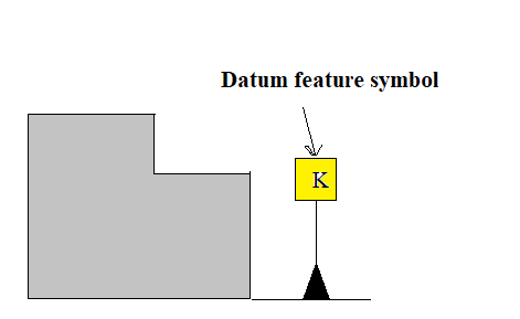
3. On the drawing and produced part below, label the following terms: Datum feature symbol Datum Datum feature Datum feature simulator | Simulated datum Surfa
3. On the drawing and produced part below, label the following terms: Datum feature symbol Datum Datum feature Datum feature simulator | Simulated datum Surfa
Elements Of Electromagnetics
7th Edition
ISBN:9780190698614
Author:Sadiku, Matthew N. O.
Publisher:Sadiku, Matthew N. O.
ChapterMA: Math Assessment
Section: Chapter Questions
Problem 1.1MA
Related questions
Question
I need help filling in the remainder of the drawing labeled in the picture below. Please only use the terms that are provided.
Refer to image.

Transcribed Image Text:### Understanding Datum Features in Technical Drawings
In the illustration below, we explore the concept of datum features by examining the labeled terms on a drawing and the corresponding produced parts.
**Labels:**
- **Datum Feature Symbol**: This is represented by a boxed letter "K" preceding the diagram. It signifies the datum feature on the part drawing.
- **Datum**: The theoretically exact point, axis, or plane derived from the datum feature. It is crucial for establishing the geometry of a part.
- **Datum Feature**: The actual part of the object used to establish a datum.
- **Datum Feature Simulator**: The tooling or equipment that simulates the datum feature for measurement, inspection, or machining.
- **Simulated Datum**: The result from using the datum feature simulator; it represents the ideal condition.
**Diagram Explanation:**
- Images on the drawing depict a green, stepped part sitting atop a gray surface plate.
- The "Datum Feature Symbol" is shown pointing to the left side of the green part.
- An arrow labeled "Surface of the part, or Datum Features" points to the top surface of the green object.
- "Surface of plate, or Simulated Datum" is annotated beside the surface plate, emphasizing the relationship between the part's geometry and the precision of its alignment during production.
- "Plane derived from surface plate, or Datum" shows that the surface plate aids in deriving the datum plane, ensuring accuracy.
- "Theoretically perfect plane, or Datum" indicates the idealized version of the datum, an essential reference for any precision work.
This understanding of datum features and their simulation is integral for precise measurement and machining in manufacturing processes.
**Image Reference**: Page 6.17
Expert Solution
Step 1
Label the given terms.

Step by step
Solved in 2 steps with 2 images

Recommended textbooks for you

Elements Of Electromagnetics
Mechanical Engineering
ISBN:
9780190698614
Author:
Sadiku, Matthew N. O.
Publisher:
Oxford University Press

Mechanics of Materials (10th Edition)
Mechanical Engineering
ISBN:
9780134319650
Author:
Russell C. Hibbeler
Publisher:
PEARSON

Thermodynamics: An Engineering Approach
Mechanical Engineering
ISBN:
9781259822674
Author:
Yunus A. Cengel Dr., Michael A. Boles
Publisher:
McGraw-Hill Education

Elements Of Electromagnetics
Mechanical Engineering
ISBN:
9780190698614
Author:
Sadiku, Matthew N. O.
Publisher:
Oxford University Press

Mechanics of Materials (10th Edition)
Mechanical Engineering
ISBN:
9780134319650
Author:
Russell C. Hibbeler
Publisher:
PEARSON

Thermodynamics: An Engineering Approach
Mechanical Engineering
ISBN:
9781259822674
Author:
Yunus A. Cengel Dr., Michael A. Boles
Publisher:
McGraw-Hill Education

Control Systems Engineering
Mechanical Engineering
ISBN:
9781118170519
Author:
Norman S. Nise
Publisher:
WILEY

Mechanics of Materials (MindTap Course List)
Mechanical Engineering
ISBN:
9781337093347
Author:
Barry J. Goodno, James M. Gere
Publisher:
Cengage Learning

Engineering Mechanics: Statics
Mechanical Engineering
ISBN:
9781118807330
Author:
James L. Meriam, L. G. Kraige, J. N. Bolton
Publisher:
WILEY