3) The op-amps circuits below all use ideal op-amps powered by V,+ = +12 V and V,- -- 12V. (Ideal means: infinite input impedance, infinite open loop gain, very low output impedance and finite output voltages.) Calculate Vout for cach circuit with Vin -+3V for all circuits: Vin Vin Vout Vout 2V 4V (A) (B) 10kf? Vin 2k? 10k? 1kf? (C) (D) Vin
3) The op-amps circuits below all use ideal op-amps powered by V,+ = +12 V and V,- -- 12V. (Ideal means: infinite input impedance, infinite open loop gain, very low output impedance and finite output voltages.) Calculate Vout for cach circuit with Vin -+3V for all circuits: Vin Vin Vout Vout 2V 4V (A) (B) 10kf? Vin 2k? 10k? 1kf? (C) (D) Vin

Related questions
Question
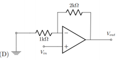
please do D

Transcribed Image Text:3)
V- = - 12V. (Ideal means: infinite input impedance, infinite open loop gain, very low
output impedance and finite output voltages.) Calculate Vout for each circuit with Vin
= +3V for all circuits:
The op-amps circuits below all use ideal op-amps powered by Vs+ =+12 V and
Vin
Vin
Vout
Vout
2V
4V
(A)
(B)
10kN
Vin
2k?
Vout
10k?
Vout
1k?
Vin
(C)
(D)
Expert Solution
Step 1
Given:
The circuit diagram is as follows:
The value of the input voltage is .
Introduction:
A non-inverting amplifier is an op-amp circuit configuration that produces an amplified output signal. This output signal of the non-inverting op-amp is in-phase with the input signal applied. In other words, a non-inverting amplifier behaves like a voltage follower circuit.

Step by step
Solved in 2 steps with 1 images
