3-Determine the output voltage in Figure 8 for each of the following failure modes: (a) L1 open (b) L2 open (c) R1 open (d) a short across R2 5 V 1 MHz L₁ m 8.0 pH L₂ mon 40 pH Figure 8 www R₁ www 100 (2 R₂ 100 Ω R3 56 Ω out
3-Determine the output voltage in Figure 8 for each of the following failure modes: (a) L1 open (b) L2 open (c) R1 open (d) a short across R2 5 V 1 MHz L₁ m 8.0 pH L₂ mon 40 pH Figure 8 www R₁ www 100 (2 R₂ 100 Ω R3 56 Ω out

Introductory Circuit Analysis (13th Edition)
13th Edition
ISBN:9780133923605
Author:Robert L. Boylestad
Publisher:Robert L. Boylestad
Chapter1: Introduction
Section: Chapter Questions
Problem 1P: Visit your local library (at school or home) and describe the extent to which it provides literature...

Related questions
Question

Transcribed Image Text:**Transcription for Educational Website**
---
**Title: Analysis of Circuit Failure Modes**
**Problem Statement:**
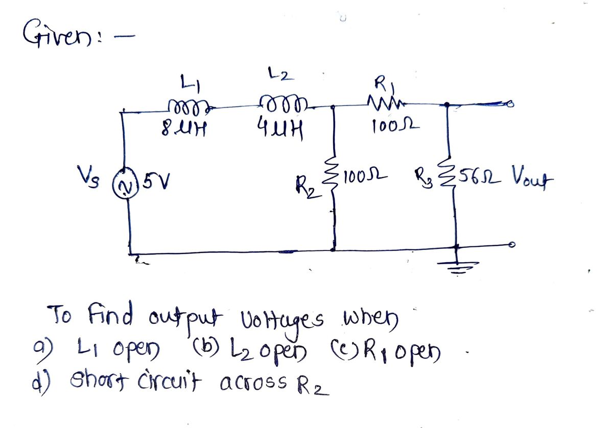
Determine the output voltage in Figure 8 for each of the following failure modes:
- (a) L1 open
- (b) L2 open
- (c) R1 open
- (d) A short across R2
**Circuit Description:**
The circuit shown in Figure 8 includes the following elements:
- A sinusoidal voltage source (Vs) with an amplitude of 5 V and frequency of 1 MHz.
- Inductor \(L_1\) with an inductance of 8.0 µH.
- Inductor \(L_2\) with an inductance of 4.0 µH.
- Resistor \(R_1\) with a resistance of 100 Ω.
- Resistor \(R_2\) with a resistance of 100 Ω.
- Resistor \(R_3\) with a resistance of 56 Ω.
The output voltage \(V_{out}\) is measured across \(R_3\).
**Figure 8 Analysis:**
The diagram shows a series of components connected in a combination of series and parallel configurations. The voltage source \(Vs\) drives the circuit through inductors \(L_1\) and \(L_2\), followed by \(R_1\). Resistor \(R_2\) is connected in parallel with \(R_3\), where the output voltage \(V_{out}\) is measured across \(R_3\). Analyzing each failure mode involves determining how interruptions or changes (such as open circuits or shorts) impact \(V_{out}\).
---
This description and analysis can help students understand the effects of different component failures on circuit performance and how to approach problem-solving in electronic circuits.
Expert Solution
Step 1: Given

Step by step
Solved in 4 steps with 3 images

Recommended textbooks for you
Introductory Circuit Analysis (13th Edition)
Electrical Engineering
ISBN:
9780133923605
Author:
Robert L. Boylestad
Publisher:
PEARSON

Delmar's Standard Textbook Of Electricity
Electrical Engineering
ISBN:
9781337900348
Author:
Stephen L. Herman
Publisher:
Cengage Learning

Programmable Logic Controllers
Electrical Engineering
ISBN:
9780073373843
Author:
Frank D. Petruzella
Publisher:
McGraw-Hill Education
Introductory Circuit Analysis (13th Edition)
Electrical Engineering
ISBN:
9780133923605
Author:
Robert L. Boylestad
Publisher:
PEARSON
Delmar's Standard Textbook Of Electricity
Electrical Engineering
ISBN:
9781337900348
Author:
Stephen L. Herman
Publisher:
Cengage Learning
Programmable Logic Controllers
Electrical Engineering
ISBN:
9780073373843
Author:
Frank D. Petruzella
Publisher:
McGraw-Hill Education

Fundamentals of Electric Circuits
Electrical Engineering
ISBN:
9780078028229
Author:
Charles K Alexander, Matthew Sadiku
Publisher:
McGraw-Hill Education

Electric Circuits. (11th Edition)
Electrical Engineering
ISBN:
9780134746968
Author:
James W. Nilsson, Susan Riedel
Publisher:
PEARSON

Engineering Electromagnetics
Electrical Engineering
ISBN:
9780078028151
Author:
Hayt, William H. (william Hart), Jr, BUCK, John A.
Publisher:
Mcgraw-hill Education,