2R< Answer: Answer: 3R 4R< Answer: ww 3R 2R Answer: Io Ja Consider the network above, with Io = 3A, V = 340V, and R = 49. a. First, a 302 resistor is connected between nodes a and b. What is the current through this resistor (arrow is down)? R R b. Next, a 5A source is connected between nodes a and b, with the current arrow pointing from a to b. What is the voltage across this source (+ at b)? Vo c. Finally, what value of a load resistance connected between a and b will dissipate the largest amount of power? d. What is the maximum possible power dissipated by the load resistance?
2R< Answer: Answer: 3R 4R< Answer: ww 3R 2R Answer: Io Ja Consider the network above, with Io = 3A, V = 340V, and R = 49. a. First, a 302 resistor is connected between nodes a and b. What is the current through this resistor (arrow is down)? R R b. Next, a 5A source is connected between nodes a and b, with the current arrow pointing from a to b. What is the voltage across this source (+ at b)? Vo c. Finally, what value of a load resistance connected between a and b will dissipate the largest amount of power? d. What is the maximum possible power dissipated by the load resistance?

Introductory Circuit Analysis (13th Edition)
13th Edition
ISBN:9780133923605
Author:Robert L. Boylestad
Publisher:Robert L. Boylestad
Chapter1: Introduction
Section: Chapter Questions
Problem 1P: Visit your local library (at school or home) and describe the extent to which it provides literature...

Related questions

Question
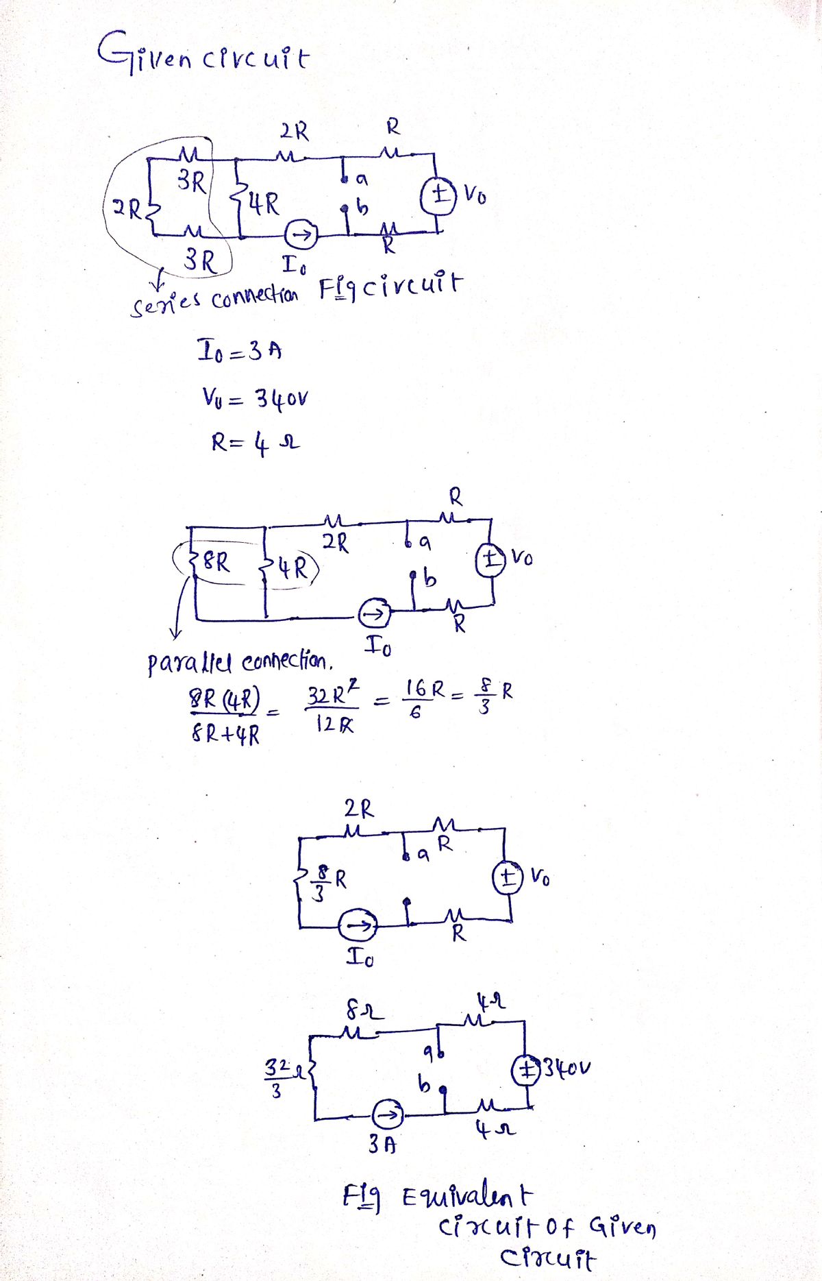
![**Circuit Diagram Description:**
The circuit includes the following components:
- Resistors: 3R, 2R, 4R, R (two 3R resistors, one 2R resistor, one 4R resistor, and two R resistors).
- A current source labeled \( I_0 = 3A \) is pointing clockwise.
- A voltage source labeled \( V_0 = 340V \).
**Educational Website Content:**
Consider the network above, with \( I_0 = 3A \), \( V_0 = 340V \), and \( R = 4\Omega \).
a. First, a \( 30\Omega \) resistor is connected between nodes \( a \) and \( b \). What is the current through this resistor (arrow is down)?
Answer: [Input box]
b. Next, a \( 5A \) source is connected between nodes \( a \) and \( b \), with the current arrow pointing from \( a \) to \( b \). What is the voltage across this source (+ at \( b \))?
Answer: [Input box]
c. Finally, what value of a load resistance connected between \( a \) and \( b \) will dissipate the largest amount of power?
Answer: [Input box]
d. What is the maximum possible power dissipated by the load resistance?
Answer: [Input box]](/v2/_next/image?url=https%3A%2F%2Fcontent.bartleby.com%2Fqna-images%2Fquestion%2F178d4f16-e840-47df-a2f3-a1f3117db472%2F7e19a4e8-5217-4646-9804-93c9ad21e792%2F79lkfbf_processed.png&w=3840&q=75)
Transcribed Image Text:**Circuit Diagram Description:**
The circuit includes the following components:
- Resistors: 3R, 2R, 4R, R (two 3R resistors, one 2R resistor, one 4R resistor, and two R resistors).
- A current source labeled \( I_0 = 3A \) is pointing clockwise.
- A voltage source labeled \( V_0 = 340V \).
**Educational Website Content:**
Consider the network above, with \( I_0 = 3A \), \( V_0 = 340V \), and \( R = 4\Omega \).
a. First, a \( 30\Omega \) resistor is connected between nodes \( a \) and \( b \). What is the current through this resistor (arrow is down)?
Answer: [Input box]
b. Next, a \( 5A \) source is connected between nodes \( a \) and \( b \), with the current arrow pointing from \( a \) to \( b \). What is the voltage across this source (+ at \( b \))?
Answer: [Input box]
c. Finally, what value of a load resistance connected between \( a \) and \( b \) will dissipate the largest amount of power?
Answer: [Input box]
d. What is the maximum possible power dissipated by the load resistance?
Answer: [Input box]
Expert Solution
Step 1

Step by step
Solved in 5 steps with 5 images

Knowledge Booster


Learn more about
Need a deep-dive on the concept behind this application? Look no further. Learn more about this topic, electrical-engineering and related others by exploring similar questions and additional content below.Recommended textbooks for you
Introductory Circuit Analysis (13th Edition)
Electrical Engineering
ISBN:
9780133923605
Author:
Robert L. Boylestad
Publisher:
PEARSON

Delmar's Standard Textbook Of Electricity
Electrical Engineering
ISBN:
9781337900348
Author:
Stephen L. Herman
Publisher:
Cengage Learning

Programmable Logic Controllers
Electrical Engineering
ISBN:
9780073373843
Author:
Frank D. Petruzella
Publisher:
McGraw-Hill Education
Introductory Circuit Analysis (13th Edition)
Electrical Engineering
ISBN:
9780133923605
Author:
Robert L. Boylestad
Publisher:
PEARSON
Delmar's Standard Textbook Of Electricity
Electrical Engineering
ISBN:
9781337900348
Author:
Stephen L. Herman
Publisher:
Cengage Learning
Programmable Logic Controllers
Electrical Engineering
ISBN:
9780073373843
Author:
Frank D. Petruzella
Publisher:
McGraw-Hill Education

Fundamentals of Electric Circuits
Electrical Engineering
ISBN:
9780078028229
Author:
Charles K Alexander, Matthew Sadiku
Publisher:
McGraw-Hill Education

Electric Circuits. (11th Edition)
Electrical Engineering
ISBN:
9780134746968
Author:
James W. Nilsson, Susan Riedel
Publisher:
PEARSON

Engineering Electromagnetics
Electrical Engineering
ISBN:
9780078028151
Author:
Hayt, William H. (william Hart), Jr, BUCK, John A.
Publisher:
Mcgraw-hill Education,