2.29 Three 10, 100 kVA, 2300/460 V, 60 Hz transformers are connected to form a 30, 2300/460 V trans- former bank. The equivalent impedance of each transformer referred to its low-voltage side is 0.045 +10.16 2. The transformer is connected to a 36 source through 30 feeders, the impedance of each feeder being 0.5 +j1.5 2. The transformer delivers full load at 460 V and 0.85 power factor lagging. (a) Draw a schematic diagram showing the transformer connection. (b) Determine the single-phase equivalent circuit. (c) Determine the sending end voltage of the 30 source. (d) Determine the transformer winding currents.
2.29 Three 10, 100 kVA, 2300/460 V, 60 Hz transformers are connected to form a 30, 2300/460 V trans- former bank. The equivalent impedance of each transformer referred to its low-voltage side is 0.045 +10.16 2. The transformer is connected to a 36 source through 30 feeders, the impedance of each feeder being 0.5 +j1.5 2. The transformer delivers full load at 460 V and 0.85 power factor lagging. (a) Draw a schematic diagram showing the transformer connection. (b) Determine the single-phase equivalent circuit. (c) Determine the sending end voltage of the 30 source. (d) Determine the transformer winding currents.

Introductory Circuit Analysis (13th Edition)
13th Edition
ISBN:9780133923605
Author:Robert L. Boylestad
Publisher:Robert L. Boylestad
Chapter1: Introduction
Section: Chapter Questions
Problem 1P: Visit your local library (at school or home) and describe the extent to which it provides literature...

Related questions

Concept explainers
Three-Phase Transformers
Three-segment transformers are a type of transformer used to transform voltages of electrical systems into three ranges. Two type transformers are shell-type transformer and core type transformer. In brief, it could be described because of the exquisite kinds of configurations.
Transformer
Ever since electricity has been created, people have started using it in its entirety. We see many types of Transformers in the neighborhoods. Some are smaller in size and some are very large. They are used according to their requirements. Many of us have seen the electrical transformer but they do not know what work they are engaged in.
Question

Transcribed Image Text:2.29
Three 10, 100 kVA, 2300/460 V, 60 Hz transformers are connected to form a 36, 2300/460 V trans-
former bank. The equivalent impedance of each transformer referred to its low-voltage side is
0.045 +10.16 2. The transformer is connected to a 36 source through 30 feeders, the impedance of
each feeder being 0.5 +j1.52. The transformer delivers full load at 460 V and 0.85 power factor
lagging.
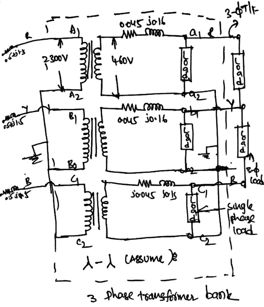
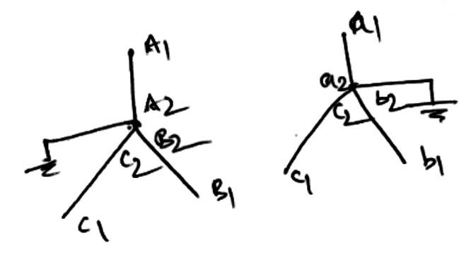
(a) Draw a schematic diagram showing the transformer connection.
(b) Determine the single-phase equivalent circuit.
(c) Determine the sending end voltage of the 30 source.
(d) Determine the transformer winding currents.
Expert Solution
Step 1: Solution a
(a) Three-phase transformer schematic diagram:
format('truetype')%3Bfont-weight%3Anormal%3Bfont-style%3Anormal%3B%7D%3C%2Fstyle%3E%3C%2Fdefs%3E%3Ctext%20font-family%3D%22Arial%22%20font-size%3D%2216%22%20text-anchor%3D%22middle%22%20x%3D%2218.5%22%20y%3D%2216%22%3ETotal%3C%2Ftext%3E%3Ctext%20font-family%3D%22Arial%22%20font-size%3D%2216%22%20text-anchor%3D%22middle%22%20x%3D%2244.5%22%20y%3D%2216%22%3E3%3C%2Ftext%3E%3Ctext%20font-family%3D%22math180fb83078ae4686c8d6275d08d%22%20font-size%3D%2216%22%20text-anchor%3D%22middle%22%20x%3D%2256.5%22%20y%3D%2216%22%3E%26%23x2212%3B%3C%2Ftext%3E%3Ctext%20font-family%3D%22Arial%22%20font-size%3D%2216%22%20text-anchor%3D%22middle%22%20x%3D%2268.5%22%20y%3D%2216%22%3E%26%23x3D5%3B%3C%2Ftext%3E%3Ctext%20font-family%3D%22Arial%22%20font-size%3D%2216%22%20text-anchor%3D%22middle%22%20x%3D%22118.5%22%20y%3D%2216%22%3Etransformer%3C%2Ftext%3E%3Ctext%20font-family%3D%22Arial%22%20font-size%3D%2216%22%20text-anchor%3D%22middle%22%20x%3D%22179.5%22%20y%3D%2216%22%3EKVA%3C%2Ftext%3E%3Ctext%20font-family%3D%22math180fb83078ae4686c8d6275d08d%22%20font-size%3D%2216%22%20text-anchor%3D%22middle%22%20x%3D%22203.5%22%20y%3D%2216%22%3E%3D%3C%2Ftext%3E%3Ctext%20font-family%3D%22Arial%22%20font-size%3D%2216%22%20text-anchor%3D%22middle%22%20x%3D%22216.5%22%20y%3D%2216%22%3E3%3C%2Ftext%3E%3Ctext%20font-family%3D%22math180fb83078ae4686c8d6275d08d%22%20font-size%3D%2216%22%20text-anchor%3D%22middle%22%20x%3D%22228.5%22%20y%3D%2216%22%3E%26%23xD7%3B%3C%2Ftext%3E%3Ctext%20font-family%3D%22Arial%22%20font-size%3D%2216%22%20text-anchor%3D%22middle%22%20x%3D%22249.5%22%20y%3D%2216%22%3E100%3C%2Ftext%3E%3Ctext%20font-family%3D%22math180fb83078ae4686c8d6275d08d%22%20font-size%3D%2216%22%20text-anchor%3D%22middle%22%20x%3D%22271.5%22%20y%3D%2216%22%3E%3D%3C%2Ftext%3E%3Ctext%20font-family%3D%22Arial%22%20font-size%3D%2216%22%20text-anchor%3D%22middle%22%20x%3D%22293.5%22%20y%3D%2216%22%3E300%3C%2Ftext%3E%3Ctext%20font-family%3D%22Arial%22%20font-size%3D%2216%22%20text-anchor%3D%22middle%22%20x%3D%22323.5%22%20y%3D%2216%22%3EKVA%3C%2Ftext%3E%3C%2Fsvg%3E)

Step by step
Solved in 4 steps with 7 images

Knowledge Booster


Learn more about
Need a deep-dive on the concept behind this application? Look no further. Learn more about this topic, electrical-engineering and related others by exploring similar questions and additional content below.Recommended textbooks for you
Introductory Circuit Analysis (13th Edition)
Electrical Engineering
ISBN:
9780133923605
Author:
Robert L. Boylestad
Publisher:
PEARSON

Delmar's Standard Textbook Of Electricity
Electrical Engineering
ISBN:
9781337900348
Author:
Stephen L. Herman
Publisher:
Cengage Learning

Programmable Logic Controllers
Electrical Engineering
ISBN:
9780073373843
Author:
Frank D. Petruzella
Publisher:
McGraw-Hill Education
Introductory Circuit Analysis (13th Edition)
Electrical Engineering
ISBN:
9780133923605
Author:
Robert L. Boylestad
Publisher:
PEARSON
Delmar's Standard Textbook Of Electricity
Electrical Engineering
ISBN:
9781337900348
Author:
Stephen L. Herman
Publisher:
Cengage Learning
Programmable Logic Controllers
Electrical Engineering
ISBN:
9780073373843
Author:
Frank D. Petruzella
Publisher:
McGraw-Hill Education

Fundamentals of Electric Circuits
Electrical Engineering
ISBN:
9780078028229
Author:
Charles K Alexander, Matthew Sadiku
Publisher:
McGraw-Hill Education

Electric Circuits. (11th Edition)
Electrical Engineering
ISBN:
9780134746968
Author:
James W. Nilsson, Susan Riedel
Publisher:
PEARSON

Engineering Electromagnetics
Electrical Engineering
ISBN:
9780078028151
Author:
Hayt, William H. (william Hart), Jr, BUCK, John A.
Publisher:
Mcgraw-hill Education,