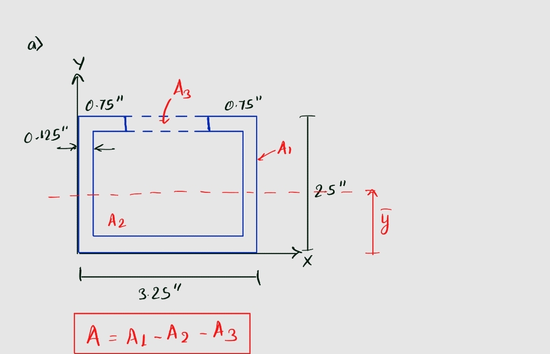
2) For the cross section shown, assume it is bending about the z-axis. a) Divide the cross section into sections and label each section, draw the reference axis, and label the y, for each section from the reference line. b) Develop Table 1 as shown in class and determine the distance from the reference axis to the neutral axis, y in in. [Ans. to Check: y = 1.03 in from the reference axis] c) Determine and label di for each section. d) Develop Table 2 as shown in class and compute the moment of inertia about the z-axis, Iz, in inº [Ans. to Check: I,= 1.017 in'] 0.75 in. 0.125 in. (typ) 3.25 in. 0.75 in. 2.50 in.
2) For the cross section shown, assume it is bending about the z-axis. a) Divide the cross section into sections and label each section, draw the reference axis, and label the y, for each section from the reference line. b) Develop Table 1 as shown in class and determine the distance from the reference axis to the neutral axis, y in in. [Ans. to Check: y = 1.03 in from the reference axis] c) Determine and label di for each section. d) Develop Table 2 as shown in class and compute the moment of inertia about the z-axis, Iz, in inº [Ans. to Check: I,= 1.017 in'] 0.75 in. 0.125 in. (typ) 3.25 in. 0.75 in. 2.50 in.
Chapter2: Loads On Structures
Section: Chapter Questions
Problem 1P
Related questions
Question

Transcribed Image Text:**Problem 2: Cross Section Analysis for Bending about the z-axis**
For the given cross section, which is assumed to be bending about the z-axis, perform the following tasks:
a) **Section Division and Reference Axis**: Divide the cross section into distinct sections. Label each section clearly. Draw the reference axis, and for each section, label the distance \( y_i \) from the reference line.
b) **Neutral Axis Distance Calculation**: Create a table (similar to a class example) to determine the distance from the reference axis to the neutral axis, denoted as \(\bar{y}\), in inches.
- **Answer to Check**: \(\bar{y} = 1.03 \, \text{in from the reference axis}\)
c) **Labeling Neutral Axis Distance (\(d_i\))**: Determine and label the \( d_i \) for each section.
d) **Moment of Inertia Calculation**: Develop another table (following class instructions) to compute the moment of inertia about the z-axis, denoted as \( I_z \), in inches to the fourth power (\( \text{in}^4\)).
- **Answer to Check**: \( I_z = 1.017 \, \text{in}^4\)
**Diagram Explanation:**
The diagram provided is a U-shaped cross section with the following dimensions:
- **Width** of each vertical side: 0.125 inches (typical thickness)
- **Outer width** of the U-section: 3.25 inches
- **Height** of the U-section: 2.50 inches
- **Depth of each horizontal flange** on top and bottom: 0.75 inches
The reference axis is denoted as \( z \). There is a central point marked, indicating the centroidal location of the cross section. Arrows indicate the distance \( y \), from the reference axis to the centroidal axis. The overall shape forms a channel with equal flanges on the top and bottom and equal lateral sides.
Expert Solution
Step 1: Divide the cross section

Step by step
Solved in 3 steps with 3 images

Knowledge Booster
Learn more about
Need a deep-dive on the concept behind this application? Look no further. Learn more about this topic, civil-engineering and related others by exploring similar questions and additional content below.Recommended textbooks for you


Structural Analysis (10th Edition)
Civil Engineering
ISBN:
9780134610672
Author:
Russell C. Hibbeler
Publisher:
PEARSON

Principles of Foundation Engineering (MindTap Cou…
Civil Engineering
ISBN:
9781337705028
Author:
Braja M. Das, Nagaratnam Sivakugan
Publisher:
Cengage Learning


Structural Analysis (10th Edition)
Civil Engineering
ISBN:
9780134610672
Author:
Russell C. Hibbeler
Publisher:
PEARSON

Principles of Foundation Engineering (MindTap Cou…
Civil Engineering
ISBN:
9781337705028
Author:
Braja M. Das, Nagaratnam Sivakugan
Publisher:
Cengage Learning

Fundamentals of Structural Analysis
Civil Engineering
ISBN:
9780073398006
Author:
Kenneth M. Leet Emeritus, Chia-Ming Uang, Joel Lanning
Publisher:
McGraw-Hill Education


Traffic and Highway Engineering
Civil Engineering
ISBN:
9781305156241
Author:
Garber, Nicholas J.
Publisher:
Cengage Learning