1 1 1 A B C 1 U6 U4 US st 4 5 2 U1 U2 U3 6 7 8 U7 D 9 LED1

Introductory Circuit Analysis (13th Edition)
13th Edition
ISBN:9780133923605
Author:Robert L. Boylestad
Publisher:Robert L. Boylestad
Chapter1: Introduction
Section: Chapter Questions
Problem 1P: Visit your local library (at school or home) and describe the extent to which it provides literature...

Related questions

Question
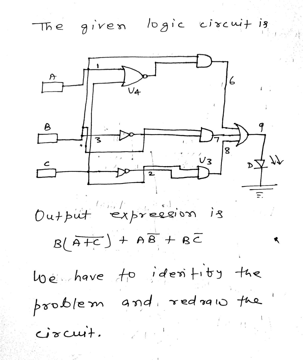
The circuit attached below is supposed to match the boolean expression attached but there is a problem with this circuit. What is the problem and redraw the circuit.

Transcribed Image Text:The image shows a Boolean algebra expression:
B(A' + C') + A'B' + B'C'
- The expression includes variables A, B, and C.
- The apostrophe (') represents the logical NOT operation (complement).
- The plus (+) symbol represents the logical OR operation.
- The absence of a symbol between variables indicates the logical AND operation.

Transcribed Image Text:This diagram illustrates a digital logic circuit using logic gates to control an LED (LED1). The circuit consists of several components labeled U1 to U7, and three input variables labeled A, B, and C, all set to logic high (1).
**Components and Connections:**
1. **Inputs:**
- A, B, C: Three inputs, each set to logic level 1.
2. **Logic Gates:**
- **U4 (OR Gate):** This gate receives inputs from A and B. The output (labeled 4) is fed into AND gate U1.
- **U5 (NOT Gate):** This gate inverts input B (labeled 3), and the output is fed into AND gate U3.
- **U6 (OR Gate):** This gate receives inputs from A and the inverted B, outputting 2 to AND gate U2.
3. **AND Gates:**
- **U1:** Receives input from the OR gate U4 (output 4) and input C. The output (6) goes to OR gate U7.
- **U2:** Receives input from OR gate U6 (output 2) and input B. The output (5) goes to OR gate U7.
- **U3:** Receives inverted input B and input C. The output (8) goes to OR gate U7.
4. **U7 (OR Gate):** Combines outputs from the AND gates U1 (6), U2 (7), and U3 (8). The resulting output (9) connects to LED1.
5. **LED1:** The LED will illuminate if any of the outputs from U1, U2, or U3 is high.
**Functionality:**
This logic circuit evaluates the inputs and performs a series of logic operations to determine whether the LED should light up. The LED (LED1) will turn on if any of the following conditions are true:
- A OR B is true AND C is true.
- A OR NOT B is true AND B is true.
- NOT B is true AND C is true.
This circuit demonstrates the combination of OR, AND, and NOT gates to achieve a specific logic function, often used in digital electronics education to illustrate how binary logic is implemented in hardware.
Expert Solution
Step 1

Step by step
Solved in 3 steps with 3 images

Knowledge Booster


Learn more about
Need a deep-dive on the concept behind this application? Look no further. Learn more about this topic, electrical-engineering and related others by exploring similar questions and additional content below.Recommended textbooks for you
Introductory Circuit Analysis (13th Edition)
Electrical Engineering
ISBN:
9780133923605
Author:
Robert L. Boylestad
Publisher:
PEARSON

Delmar's Standard Textbook Of Electricity
Electrical Engineering
ISBN:
9781337900348
Author:
Stephen L. Herman
Publisher:
Cengage Learning

Programmable Logic Controllers
Electrical Engineering
ISBN:
9780073373843
Author:
Frank D. Petruzella
Publisher:
McGraw-Hill Education
Introductory Circuit Analysis (13th Edition)
Electrical Engineering
ISBN:
9780133923605
Author:
Robert L. Boylestad
Publisher:
PEARSON
Delmar's Standard Textbook Of Electricity
Electrical Engineering
ISBN:
9781337900348
Author:
Stephen L. Herman
Publisher:
Cengage Learning
Programmable Logic Controllers
Electrical Engineering
ISBN:
9780073373843
Author:
Frank D. Petruzella
Publisher:
McGraw-Hill Education

Fundamentals of Electric Circuits
Electrical Engineering
ISBN:
9780078028229
Author:
Charles K Alexander, Matthew Sadiku
Publisher:
McGraw-Hill Education

Electric Circuits. (11th Edition)
Electrical Engineering
ISBN:
9780134746968
Author:
James W. Nilsson, Susan Riedel
Publisher:
PEARSON

Engineering Electromagnetics
Electrical Engineering
ISBN:
9780078028151
Author:
Hayt, William H. (william Hart), Jr, BUCK, John A.
Publisher:
Mcgraw-hill Education,