Machine Tool Practices (11th Edition)
11th Edition
ISBN: 9780134893501
Author: Richard R. Kibbe, Roland O. Meyer, Jon Stenerson, Kelly Curran
Publisher: PEARSON
expand_more
expand_more
format_list_bulleted
Question
Chapter A.9, Problem 1.1QC
To determine
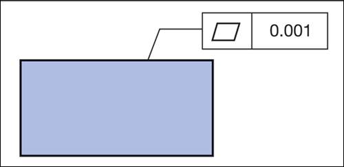
The value of form tolerance for the following figure.
Expert Solution & Answer
Answer to Problem 1.1QC
The value of flatness form tolerance for the given figure is
Explanation of Solution
A basic geometric tolerance which used to determine the form of part is given by form tolerance.
The types of form tolerances are as:
- Straightness:
- Flatness
- Roundness
- Cylindricity


In the given figure, the symbol implies that it is a flatness tolerance. Hence, the form tolerance for flatness of the given figure is
Conclusion:
Hence, the flatness tolerance for the given figure is
Want to see more full solutions like this?
Subscribe now to access step-by-step solutions to millions of textbook problems written by subject matter experts!
Students have asked these similar questions
Can you provide steps and an explaination on how the height value to calculate the Pressure at point B is (-5-3.5) and the solution is 86.4kPa.
PROBLEM 3.46
The solid cylindrical rod BC of length L = 600
mm is attached to the rigid lever AB of length a
= 380 mm and to the support at C. When a 500
N force P is applied at A, design specifications
require that the displacement of A not exceed
25 mm when a 500 N force P is applied at A
For the material indicated determine the
required diameter of the rod.
Aluminium: Tall = 65 MPa, G = 27 GPa.
A
Find the equivalent mass of the rocker arm assembly with respect to the x coordinate.
k₁
mi
m2
k₁
Chapter A Solutions
Machine Tool Practices (11th Edition)
Ch. A.1 - Prob. 1STCh. A.1 - Prob. 2STCh. A.1 - Companies are looking for people with good...Ch. A.1 - Prob. 4STCh. A.1 - Prob. 5STCh. A.1 - Prob. 6STCh. A.1 - Prob. 7STCh. A.1 - Prob. 8STCh. A.2 - Prob. 1STCh. A.2 - Prob. 2ST
Ch. A.2 - Prob. 3STCh. A.2 - Prob. 4STCh. A.2 - Prob. 5STCh. A.2 - Prob. 6STCh. A.2 - Prob. 7STCh. A.3 - What is the primary piece of safety equipment in...Ch. A.3 - Prob. 2STCh. A.3 - Prob. 3STCh. A.3 - Prob. 4STCh. A.3 - What hazards exist from coolants, oils, and...Ch. A.3 - Prob. 6STCh. A.3 - Prob. 7STCh. A.3 - Prob. 8STCh. A.3 - Prob. 9STCh. A.3 - Prob. 10STCh. A.3 - Prob. 11STCh. A.4 - Define the term pitch diameter.Ch. A.4 - Name two ways to measure a thread.Ch. A.4 - What is the rule of thumb for the length of...Ch. A.4 - Describe when class two fits are used.Ch. A.4 - Describe UNC and UNF.Ch. A.4 - What is the formula for calculating the OD of a...Ch. A.4 - When are stud bolts used?Ch. A.4 - Prob. 8STCh. A.4 - Explain two reasons why flat washers are used.Ch. A.4 - What is the purpose of a helical spring lock...Ch. A.4 - When is an internal-external tooth lock washer...Ch. A.4 - When are dowel pins used?Ch. A.4 - When are taper pins used?Ch. A.4 - When are roll pins used?Ch. A.4 - What are retaining lings?Ch. A.4 - Prob. 16STCh. A.4 - Prob. 17STCh. A.4 - Prob. 18STCh. A.5 - Prob. 1STCh. A.5 - Prob. 2STCh. A.5 - Prob. 3STCh. A.5 - Prob. 4STCh. A.5 - Prob. 5STCh. A.5 - Prob. 6STCh. A.6 - Prob. 1STCh. A.6 - Prob. 2STCh. A.6 - Prob. 3STCh. A.6 - Prob. 4STCh. A.6 - Prob. 5STCh. A.6 - Prob. 6STCh. A.6 - Prob. 7STCh. A.6 - Prob. 8STCh. A.6 - Prob. 9STCh. A.6 - Prob. 10STCh. A.7 - Prob. 1STCh. A.7 - Prob. 2STCh. A.7 - Prob. 3STCh. A.7 - Prob. 4STCh. A.7 - Prob. 5STCh. A.7 - Prob. 6STCh. A.7 - Prob. 7STCh. A.7 - Prob. 8STCh. A.7 - Prob. 9STCh. A.7 - Prob. 10STCh. A.8 - Prob. 1STCh. A.8 - Prob. 2STCh. A.8 - Prob. 3STCh. A.8 - Prob. 4STCh. A.8 - Prob. 5STCh. A.8 - Prob. 6STCh. A.8 - Prob. 7STCh. A.8 - Prob. 8STCh. A.8 - Prob. 9STCh. A.8 - Prob. 10STCh. A.8 - Prob. 11STCh. A.9 - Prob. 1.1QCCh. A.9 - Prob. 1.2QCCh. A.9 - Prob. 1.3QCCh. A.9 - Prob. 1.4QCCh. A.9 - Prob. 1.5QCCh. A.9 - Prob. 1.6QCCh. A.9 - Prob. 2.1QCCh. A.9 - Prob. 2.2QCCh. A.9 - Prob. 3.1QCCh. A.9 - Prob. 3.2QCCh. A.9 - Prob. 4.1QCCh. A.9 - Prob. 4.2QCCh. A.9 - Prob. 4.3QCCh. A.9 - Prob. 1STCh. A.9 - Prob. 2STCh. A.9 - Prob. 3STCh. A.9 - Prob. 4STCh. A.9 - Prob. 5STCh. A.9 - Prob. 6ST
Knowledge Booster

Similar questions
- 2. Figure below shows a U-tube manometer open at both ends and containing a column of liquid mercury of length l and specific weight y. Considering a small displacement x of the manometer meniscus from its equilibrium position (or datum), determine the equivalent spring constant associated with the restoring force. Datum Area, Aarrow_forward1. The consequences of a head-on collision of two automobiles can be studied by considering the impact of the automobile on a barrier, as shown in figure below. Construct a mathematical model (i.e., draw the diagram) by considering the masses of the automobile body, engine, transmission, and suspension and the elasticity of the bumpers, radiator, sheet metal body, driveline, and engine mounts.arrow_forward3.) 15.40 – Collar B moves up at constant velocity vB = 1.5 m/s. Rod AB has length = 1.2 m. The incline is at angle = 25°. Compute an expression for the angular velocity of rod AB, ė and the velocity of end A of the rod (✓✓) as a function of v₂,1,0,0. Then compute numerical answers for ȧ & y_ with 0 = 50°.arrow_forward
- 2.) 15.12 The assembly shown consists of the straight rod ABC which passes through and is welded to the grectangular plate DEFH. The assembly rotates about the axis AC with a constant angular velocity of 9 rad/s. Knowing that the motion when viewed from C is counterclockwise, determine the velocity and acceleration of corner F.arrow_forward500 Q3: The attachment shown in Fig.3 is made of 1040 HR. The static force is 30 kN. Specify the weldment (give the pattern, electrode number, type of weld, length of weld, and leg size). Fig. 3 All dimension in mm 30 kN 100 (10 Marks)arrow_forward(read image) (answer given)arrow_forward
- A cylinder and a disk are used as pulleys, as shown in the figure. Using the data given in the figure, if a body of mass m = 3 kg is released from rest after falling a height h 1.5 m, find: a) The velocity of the body. b) The angular velocity of the disk. c) The number of revolutions the cylinder has made. T₁ F Rd = 0.2 m md = 2 kg T T₂1 Rc = 0.4 m mc = 5 kg ☐ m = 3 kgarrow_forward(read image) (answer given)arrow_forward11-5. Compute all the dimensional changes for the steel bar when subjected to the loads shown. The proportional limit of the steel is 230 MPa. 265 kN 100 mm 600 kN 25 mm thickness X Z 600 kN 450 mm E=207×103 MPa; μ= 0.25 265 kNarrow_forward
- T₁ F Rd = 0.2 m md = 2 kg T₂ Tz1 Rc = 0.4 m mc = 5 kg m = 3 kgarrow_forward2. Find a basis of solutions by the Frobenius method. Try to identify the series as expansions of known functions. (x + 2)²y" + (x + 2)y' - y = 0 ; Hint: Let: z = x+2arrow_forward1. Find a power series solution in powers of x. y" - y' + x²y = 0arrow_forward
arrow_back_ios
SEE MORE QUESTIONS
arrow_forward_ios
Recommended textbooks for you
 Elements Of ElectromagneticsMechanical EngineeringISBN:9780190698614Author:Sadiku, Matthew N. O.Publisher:Oxford University Press
 Mechanics of Materials (10th Edition)Mechanical EngineeringISBN:9780134319650Author:Russell C. HibbelerPublisher:PEARSON
 Thermodynamics: An Engineering ApproachMechanical EngineeringISBN:9781259822674Author:Yunus A. Cengel Dr., Michael A. BolesPublisher:McGraw-Hill Education
 Control Systems EngineeringMechanical EngineeringISBN:9781118170519Author:Norman S. NisePublisher:WILEY
 Mechanics of Materials (MindTap Course List)Mechanical EngineeringISBN:9781337093347Author:Barry J. Goodno, James M. GerePublisher:Cengage Learning
 Engineering Mechanics: StaticsMechanical EngineeringISBN:9781118807330Author:James L. Meriam, L. G. Kraige, J. N. BoltonPublisher:WILEY
Elements Of Electromagnetics
Mechanical Engineering
ISBN:9780190698614
Author:Sadiku, Matthew N. O.
Publisher:Oxford University Press
Mechanics of Materials (10th Edition)
Mechanical Engineering
ISBN:9780134319650
Author:Russell C. Hibbeler
Publisher:PEARSON
Thermodynamics: An Engineering Approach
Mechanical Engineering
ISBN:9781259822674
Author:Yunus A. Cengel Dr., Michael A. Boles
Publisher:McGraw-Hill Education
Control Systems Engineering
Mechanical Engineering
ISBN:9781118170519
Author:Norman S. Nise
Publisher:WILEY
Mechanics of Materials (MindTap Course List)
Mechanical Engineering
ISBN:9781337093347
Author:Barry J. Goodno, James M. Gere
Publisher:Cengage Learning
Engineering Mechanics: Statics
Mechanical Engineering
ISBN:9781118807330
Author:James L. Meriam, L. G. Kraige, J. N. Bolton
Publisher:WILEY