
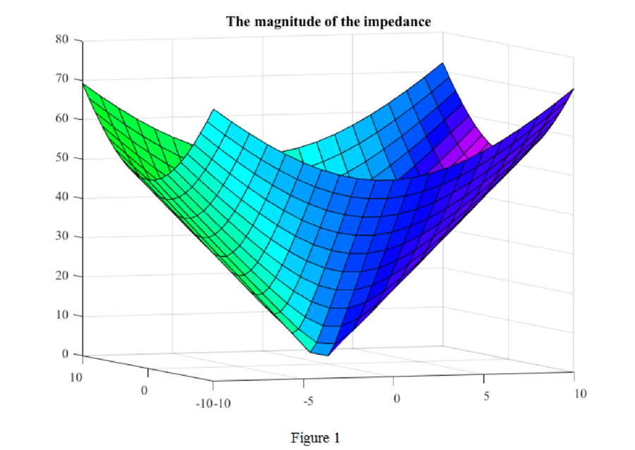
Plot the magnitude of the impedance
Answer to Problem 1P
The magnitude of the impedance as a function of
Explanation of Solution
Given data:
The admittance is,
Calculation:
The admittance is given by,
Substitute
Finding the magnitude of the above function,
Matlab code for the Impedance model:
sigma = linspace(-10,10,21);
omega = linspace(-10,10,21);
[X, Y] = meshgrid(sigma,omega);
Z = abs(2 + 5*X + j*5*Y);
colormap(hsv);
s = [-5 3 8];
surfl(X,Y,Z,s);
view (-20,5)
Matlab output:
The plot for the magnitude of given impedance is shown in Figure 1.
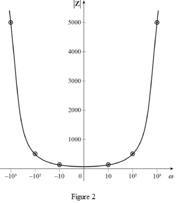
Sketch for
Consider the admittance,
Replace
Taking magnitude,
For various values of
Sketch for
Consider the admittance,
Replace
For various values of
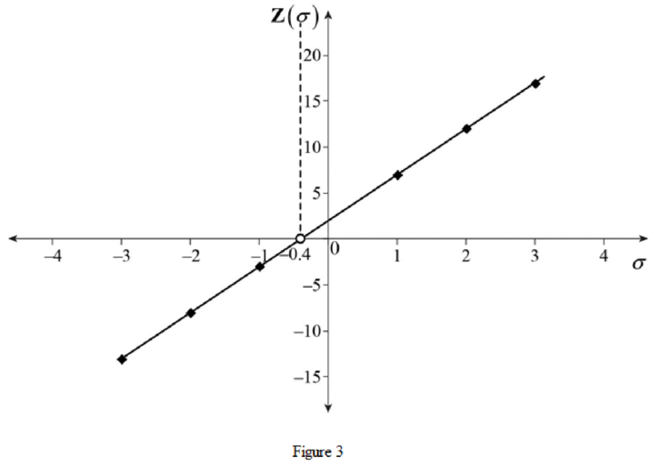
Conclusion:
Thus, the magnitude of the impedance as a function of
Want to see more full solutions like this?
Chapter A8 Solutions
ENGINEERING CIRCUIT...(LL)>CUSTOM PKG.<

- 5) Find the value of voltage V, and V₂ using Loop analysis. 5A + 4 34 ww 8 2 www 3A m 4 38 + 23V₂ 1/2 + ±) 12Varrow_forward4) Find the valve of voltage Vx using Loop analysis. 2A ( 1 3 w + 234 OV + 123arrow_forward3 Write but do not solve the set of Loop equations for this circuit www 4 १ह 15 ww 5 124 + ☹ 33 M 7A www 6 103 23 راح +arrow_forward
 Introductory Circuit Analysis (13th Edition)Electrical EngineeringISBN:9780133923605Author:Robert L. BoylestadPublisher:PEARSON
 Delmar's Standard Textbook Of ElectricityElectrical EngineeringISBN:9781337900348Author:Stephen L. HermanPublisher:Cengage Learning
 Programmable Logic ControllersElectrical EngineeringISBN:9780073373843Author:Frank D. PetruzellaPublisher:McGraw-Hill Education
 Fundamentals of Electric CircuitsElectrical EngineeringISBN:9780078028229Author:Charles K Alexander, Matthew SadikuPublisher:McGraw-Hill Education
 Electric Circuits. (11th Edition)Electrical EngineeringISBN:9780134746968Author:James W. Nilsson, Susan RiedelPublisher:PEARSON
 Engineering ElectromagneticsElectrical EngineeringISBN:9780078028151Author:Hayt, William H. (william Hart), Jr, BUCK, John A.Publisher:Mcgraw-hill Education,