
Videos
Consider a Mach 4 airflow at a pressure of 1 atm. We wish to slow this flow to subsonic speed through a system of shock waves with as small a loss in total pressure as possible. Compare the loss in total pressure for the following three shock systems:
a. A single normal shock wave
b. An oblique shock with a deflection angle of
c. An oblique shock with a deflection angle of
From the results of (a), (b), and (c), what can you induce about the efficiency of the various shock systems?
(a)
The comparison in total pressure loss for the single normal shock wave.
Answer to Problem 9.8P
The loss in pressure is
Explanation of Solution
Given:
The Mach number is
The pressure is
Formula used:
The expression for
The expression for
The expression for loss in pressure is given as,
Calculation:
The pressure
The pressure
The loss in pressure can be calculated as,
Conclusion:
Therefore, the loss in pressure is
(b)
The comparison in pressure for an oblique shock with a deflection angle of
Answer to Problem 9.8P
The loss in pressure is
Explanation of Solution
Given:
The Mach number is
The pressure is
The deflection angle of oblique shock wave is
Formula used:
The expression for
The expression for
The expression for
The expression for loss in pressure is given as,
Calculation:
From
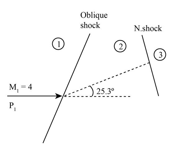
Figure (1)
The Mach number
The pressure ratio for Mach number
From appendix B
The Mach number
The pressure ratio for Mach number
The pressure
The pressure loss can be calculated as,
Conclusion:
Therefore, the loss in pressure is
(c)
The comparison in pressure for the an oblique shock with a deflection angle of
Answer to Problem 9.8P
The loss in pressure is
Explanation of Solution
Given:
The Mach number is
The pressure is
The deflection angle of second oblique shock wave is
Formula used:
The expression for the Mach number
The expression for Mach number
The expression for the pressure
The expression for loss in pressure is given as,
Calculation:
From
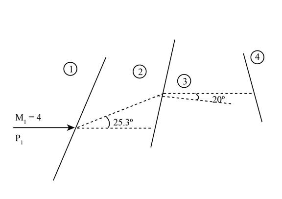
Figure (2)
The Mach number
The pressure ratio for Mach number from appendix B is given as,
Refer to appendix B
The Mach number
The pressure ratio for Mach number
The pressure
The pressure loss can be calculated as,
From a, b and c it is clear that the most efficient way to decrease supersonic flow to subsonic flow is through a combination of supersonic diffuser and then normal shock wave at the end.
Conclusion:
Therefore, the loss in pressure is
Want to see more full solutions like this?
Chapter 9 Solutions
Loose Leaf for Fundamentals of Aerodynamics


- Problem (13): A pump is being used to lift water from the bottom tank to the top tank in a galvanized iron pipe at a discharge (Q). The length and diameter of the pipe section from the bottom tank to the pump are (L₁) and (d₁), respectively. The length and diameter of the pipe section from the pump to the top tank are (L2) and (d2), respectively. Given the values of Q [L/s], L₁ [m], d₁ [m], L₂ [m], d₂ [m], calculate total head loss due to friction (i.e., major loss) in the pipe (hmajor-loss) in [cm]. Givens: L₁,d₁ Pump L₂,d2 오 0.533 lit/s L1 = 6920.729 m d1 = 1.065 m L2 = 70.946 m d2 0.072 m Answers: (1) 3.069 cm (2) 3.914 cm ( 3 ) 2.519 cm ( 4 ) 1.855 cm TABLE 8.1 Equivalent Roughness for New Pipes Pipe Riveted steel Concrete Wood stave Cast iron Galvanized iron Equivalent Roughness, & Feet Millimeters 0.003-0.03 0.9-9.0 0.001-0.01 0.3-3.0 0.0006-0.003 0.18-0.9 0.00085 0.26 0.0005 0.15 0.045 0.000005 0.0015 0.0 (smooth) 0.0 (smooth) Commercial steel or wrought iron 0.00015 Drawn…arrow_forwardThe flow rate is 12.275 Liters/s and the diameter is 6.266 cm.arrow_forwardAn experimental setup is being built to study the flow in a large water main (i.e., a large pipe). The water main is expected to convey a discharge (Qp). The experimental tube will be built at a length scale of 1/20 of the actual water main. After building the experimental setup, the pressure drop per unit length in the model tube (APm/Lm) is measured. Problem (20): Given the value of APm/Lm [kPa/m], and assuming pressure coefficient similitude, calculate the drop in the pressure per unit length of the water main (APP/Lp) in [Pa/m]. Givens: AP M/L m = 590.637 kPa/m meen Answers: ( 1 ) 59.369 Pa/m ( 2 ) 73.83 Pa/m (3) 95.443 Pa/m ( 4 ) 44.444 Pa/m *******arrow_forward
- Find the reaction force in y if Ain = 0.169 m^2, Aout = 0.143 m^2, p_in = 0.552 atm, Q = 0.367 m^3/s, α = 31.72 degrees. The pipe is flat on the ground so do not factor in weight of the pipe and fluid.arrow_forwardFind the reaction force in x if Ain = 0.301 m^2, Aout = 0.177 m^2, p_in = 1.338 atm, Q = 0.669 m^3/s, and α = 37.183 degreesarrow_forwardProblem 5: Three-Force Equilibrium A structural connection at point O is in equilibrium under the action of three forces. • • . Member A applies a force of 9 kN vertically upward along the y-axis. Member B applies an unknown force F at the angle shown. Member C applies an unknown force T along its length at an angle shown. Determine the magnitudes of forces F and T required for equilibrium, assuming 0 = 90° y 9 kN Aarrow_forward
- Problem 19: Determine the force in members HG, HE, and DE of the truss, and state if the members are in tension or compression. 4 ft K J I H G B C D E F -3 ft -3 ft 3 ft 3 ft 3 ft- 1500 lb 1500 lb 1500 lb 1500 lb 1500 lbarrow_forwardProblem 14: Determine the reactions at the pin A, and the tension in cord. Neglect the thickness of the beam. F1=26kN F2 13 12 80° -2m 3marrow_forwardProblem 22: Determine the force in members GF, FC, and CD of the bridge truss and state if the members are in tension or compression. F 15 ft B D -40 ft 40 ft -40 ft 40 ft- 5 k 10 k 15 k 30 ft Earrow_forward
- Problem 20: Determine the force in members BC, HC, and HG. After the truss is sectioned use a single equation of equilibrium for the calculation of each force. State if the members are in tension or compression. 5 kN 4 kN 4 kN 3 kN 2 kN B D E F 3 m -5 m- -5 m- 5 m 5 m-arrow_forwardAn experimental setup is being built to study the flow in a large water main (i.e., a large pipe). The water main is expected to convey a discharge (Qp). The experimental tube will be built at a length scale of 1/20 of the actual water main. After building the experimental setup, the pressure drop per unit length in the model tube (APm/Lm) is measured. Problem (19): Given the value of Qp [m³/s], and assuming Reynolds number similitude between the water main and experimental tube, calculate the flow rate in the model tube (Qm) in [lit/s]. = 30.015 m^3/sarrow_forwardProblem 11: The lamp has a weight of 15 lb and is supported by the six cords connected together as shown. Determine the tension in each cord and the angle 0 for equilibrium. Cord BC is horizontal. E 30° B 60° Aarrow_forward
 Elements Of ElectromagneticsMechanical EngineeringISBN:9780190698614Author:Sadiku, Matthew N. O.Publisher:Oxford University Press
 Mechanics of Materials (10th Edition)Mechanical EngineeringISBN:9780134319650Author:Russell C. HibbelerPublisher:PEARSON
 Thermodynamics: An Engineering ApproachMechanical EngineeringISBN:9781259822674Author:Yunus A. Cengel Dr., Michael A. BolesPublisher:McGraw-Hill Education
 Control Systems EngineeringMechanical EngineeringISBN:9781118170519Author:Norman S. NisePublisher:WILEY
 Mechanics of Materials (MindTap Course List)Mechanical EngineeringISBN:9781337093347Author:Barry J. Goodno, James M. GerePublisher:Cengage Learning
 Engineering Mechanics: StaticsMechanical EngineeringISBN:9781118807330Author:James L. Meriam, L. G. Kraige, J. N. BoltonPublisher:WILEY