
(a)
Interpretation:
The circulation rate of refrigerant for the given system is to be calculated.
Concept introduction:
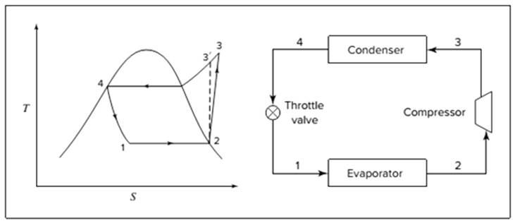
Below shown diagram represents vapor-compression refrigeration cycle on a
The line
The equations used to calculate the heat absorbed in evaporator and the heat rejected in condenser are:
The work of compression is:
The coefficient of performance is:
The rate of circulation of refrigerant,
For Carnot refrigeration cycle, highest possible value of
(b)
Interpretation:
The reduction in the circulation rate is to be calculated if throttle valve is replaced by a turbine where the refrigerant expands isentropically.
Concept introduction:
Below shown diagram represents vapor-compression refrigeration cycle on a
The line

The equations used to calculate the heat absorbed in evaporator and the heat rejected in condenser are:
The work of compression is:
The coefficient of performance is:
The rate of circulation of refrigerant,
For Carnot refrigeration cycle, highest possible value of
(c)
Interpretation:
If the cycle of (a) is modified, from the condenser if liquid enters the exchanger at
Concept introduction:
Below shown diagram represents vapor-compression refrigeration cycle on a
The line

The equations used to calculate the heat absorbed in evaporator and the heat rejected in condenser are:
The work of compression is:
The coefficient of performance is:
The rate of circulation of refrigerant,
For Carnot refrigeration cycle, highest possible value of
(d)
Interpretation:
The coefficient of performance for all the parts (a), (b), and (c) are to be calculated for isentropic compression.
Concept introduction:
Below shown diagram represents vapor-compression refrigeration cycle on a
The line

The equations used to calculate the heat absorbed in evaporator and the heat rejected in condenser are:
The work of compression is:
The coefficient of performance is:
The rate of circulation of refrigerant,
For Carnot refrigeration cycle, highest possible value of
Want to see the full answer?
Check out a sample textbook solution
Chapter 9 Solutions
INTRO.TO CHEM.ENGR.THERMO.-EBOOK>I<

- chemical engineering. The answer is minus 1.26 KJ/mol for H(3). Demonstrate the reference state to the process state and calculations. I only need help for determing that variable.arrow_forwardExhaust gas from a power plant passes through a 15-by-20-it rectangular duct at an average velocity of 50 ft/s. The total length of duct is 250 ft and there are two 90° bends.The gas is at 180°F and about 1 atm, and the properties are similar to those of air. Calculate the pressure drop in the duet and the power required to overcome pressure losses.arrow_forwardUntuk sistem gas etilena (1)/propilena (2), estimasi (f^1, f^2, $^1, dan ^2 pada t = 150°C, P = 30 bar, dan y1 = 0,35; kij = 0. (a) Dengan menerapkan Persamaan (10.63). (b) Dengan asumsi bahwa campuran adalah lingkungan idealarrow_forward
- Only focus on H(3), which is the specific enthalpy for nitrogen gas. chemical engineeringarrow_forwardchemical engineering. Only focus on H(3), which is the nitrogen gas. Start with the reference state to the process state. Be thorough to the fullestarrow_forwardacetone with these parameters: po:=101325; #Standard atmospheric pressure in PaTfo:=273.15-94.45; #Melting temperature in K Tvo:=273.15+56.15; #Boiling temperature in K Hv:=31270; #Enthalpy of vaporization in J/molR:=8.314; #Gas Constant in J/mol*KNLe:=1.76; #Lewis number for acetoneMw:= 0.05808 ; #kg/mol molecular weight of acetoneW0:= 0.15; Wsp:=0.005;Am:= 0.12; #m^2/kg dry solid for the exposed wet areah:= 11; #W/m^2K for heat transfer coefficienttau__min:= Hv*(W0-Wsp)/Mw/Am/h/(T8-TS); tau__min/60;arrow_forward
- chemical engineering Material-energy balance. Only focus on the nitrogen gas, which is H(3)arrow_forward1. The settling chamber, shown schematically in Figure 2E1.1, is used as a primary separation device in the removal of dust particles of density 1500 kg/m³ from a gas of density 0:7 kg/m³ and viscosity 1.90 x 10⁻⁵ Pa s. Gas inlet Elevation Gas Gas exit exit H Collection surface -W Section X-X Dimensions: H=3m L = 10 m W=2m Figure 2E1.1 Schematic diagram of settling chamber Assuming Stokes' law applies, show that the efficiency of collection of particles of size x is given by the expression collection efficiency, x = x²8(pp - Pi)L 18μHU where U is the uniform gas velocity through the parallel-sided section of the chamber. State any other assumptions made. (b) What is the upper limit of particle size for which Stokes' law applies? (c) When the volumetric flow rate of gas is 0.9 m³/s, and the dimensions of the chamber are those shown in Figure 2E1.1, determine the collection efficiency for spherical particles of diameter 30 mm.arrow_forwardCan you answer this sequantially correct like show me the full process. Also, since it is chemical engineering related problem a perry's handbook is used. Thank youarrow_forward
- chemical engineering Demonstrate how each specific enthalpy was calculated, from the reference state to the process state. Be thorough to the fullest. This is a material-energy balance. The answers are H(1) = 35.7 KJ/kmol, H(2) = 32.0 KJ/kmol, and H(3) = -1.26 KJ/kmol.arrow_forwardheat and mass transfer:arrow_forwardChemical Engineering. Be thorough to the fullest for the three enthalpies. H(1) = 35.7 kj/kmol H(2) =32.0 Kj/kmol H(3)= -1.26 Kj/kmolarrow_forward
 Introduction to Chemical Engineering Thermodynami...Chemical EngineeringISBN:9781259696527Author:J.M. Smith Termodinamica en ingenieria quimica, Hendrick C Van Ness, Michael Abbott, Mark SwihartPublisher:McGraw-Hill Education
 Elementary Principles of Chemical Processes, Bind...Chemical EngineeringISBN:9781118431221Author:Richard M. Felder, Ronald W. Rousseau, Lisa G. BullardPublisher:WILEY
 Elements of Chemical Reaction Engineering (5th Ed...Chemical EngineeringISBN:9780133887518Author:H. Scott FoglerPublisher:Prentice Hall
 Industrial Plastics: Theory and ApplicationsChemical EngineeringISBN:9781285061238Author:Lokensgard, ErikPublisher:Delmar Cengage Learning
 Unit Operations of Chemical EngineeringChemical EngineeringISBN:9780072848236Author:Warren McCabe, Julian C. Smith, Peter HarriottPublisher:McGraw-Hill Companies, The