
EE 98: Fundamentals of Electrical Circuits - With Connect Access
6th Edition
ISBN: 9781259981807
Author: Alexander
Publisher: MCG
expand_more
expand_more
format_list_bulleted
Videos
Textbook Question
Chapter 9, Problem 42P
Calculate vo(t) in the circuit of Fig. 9.49.
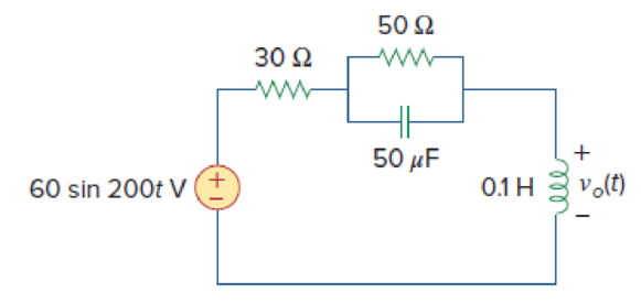
Figure 9.49
Expert Solution & Answer
Want to see the full answer?
Check out a sample textbook solution
Students have asked these similar questions
For the circuit shown in Figure (1). Solve the following: (
A. What type of logic does it represent?
C. Explain the function of D1.
B. What type of logic family does it belong to?
D. Explain the importance of DL.
E. How many stages it has? Explain the function of each one.
F. Construct the truth table and explain it briefly.
G.How can you convert this circuit to an open collector form? Explain and sketch it.
H.How can you convert this circuit to a tri-state form? Explain and sketch it.
I. How can you prevent the transistors from being saturated?
J. Which transistor should be modified to convert this circuit to a 4-inputs NAND?
Explain and sketch it.
K.Convert this circuit to a 2-inputs NOR gate and draw it.
R-1200
R-4.2K
R-1.5K
R-IK
Figure (1)
lour
e Your
E. How many stages it has? Explain the function of each one.
F. Construct the truth table and explain it briefly.
G.How can you convert this circuit to an open collector form? Explain and sketch it.
H.How can you convert this circuit to a tri-state form? Explain and sketch it.
I. How can you prevent the transistors from being saturated?
J. Which transistor should be modified to convert this circuit to a 4-inputs NAND?
Explain and sketch it.
K.Convert this circuit to a 2-inputs NOR gate and draw it.
R-4.2K
W
R-1200
R-1.5K
R-IK
Figure (1)
JOUT
e Your
1. Determine the z-transform, including the region of convergence (ROC), of the following signals:
a)x[n={3,0,0,0,0,51-4}
b) x2[n] = ((1/3)^n ,n ≥0
2", n < 0
c) X3[n]= (1/3)^n- 2", n ≥ 0
0, n < 0
Chapter 9 Solutions
EE 98: Fundamentals of Electrical Circuits - With Connect Access
Ch. 9.2 - Practice Problem 9.1 Given the sinusoid 45 cos(5t...Ch. 9.2 - Practice Problem 9.2 Find the phase angle between...Ch. 9.3 - Prob. 3PPCh. 9.3 - Express these sinusoids as phasors: (a)...Ch. 9.3 - Find the sinusoids corresponding to these phasors:...Ch. 9.3 - If v1=10sint30V and v2=20cost+45V, find v=v1+v2.Ch. 9.3 - Prob. 7PPCh. 9.4 - If voltage v=25sin100t15V is applied to a 50F...Ch. 9.5 - Refer to Fig. 9.17. Determine v(t) and i(t).Ch. 9.7 - Determine the input impedance of the circuit in...
Ch. 9.7 - Calculate vo in the circuit of Fig. 9.27. Figure...Ch. 9.7 - Find I in the circuit of Fig. 9.30. Figure 9.30Ch. 9.8 - Design an RC circuit to provide a 90 lagging phase...Ch. 9.8 - Refer to the RL circuit in Fig. 9.36. If 10 V is...Ch. 9.8 - In the ac bridge circuit of Fig. 9.37, suppose...Ch. 9 - Which of the following is not a right way to...Ch. 9 - A function that repeats itself after fixed...Ch. 9 - Which of these frequencies has the shorter period?...Ch. 9 - If v1 = 30 sin(t + 10) and v2 = 20 sin(t + 50),...Ch. 9 - The voltage across an inductor leads the current...Ch. 9 - The imaginary part of impedance is called:...Ch. 9 - The impedance of a capacitor increases with...Ch. 9 - At what frequency will the output voltage v0(t) in...Ch. 9 - A series RC circuit has VR = 12 V and VC = 5 V....Ch. 9 - A series RCL circuit has R = 30 , XC = 50 , and XL...Ch. 9 - Given the sinusoidal voltage v(t) = 50 cos (30t +...Ch. 9 - A current source in a linear circuit has...Ch. 9 - Express the following functions in cosine form:...Ch. 9 - Design a problem to help other students better...Ch. 9 - Given v1=45sint+30V and v2=50cost30V, determine...Ch. 9 - For the following pairs of sinusoids, determine...Ch. 9 - If f() = cos + j sin , show that f() = ej.Ch. 9 - Calculate these complex numbers and express your...Ch. 9 - Evaluate the following complex numbers and leave...Ch. 9 - Design a problem to help other students better...Ch. 9 - Find the phasors corresponding to the following...Ch. 9 - Let X=440 and Y=2030. Evaluate the following...Ch. 9 - Evaluate the following complex numbers: (a)...Ch. 9 - Simplify the following expression: (a)...Ch. 9 - Evaluate these determinants: (a) 10+j62j351+j (b)...Ch. 9 - Prob. 16PCh. 9 - Two voltages v1 and v2 appear in series so that...Ch. 9 - Obtain the sinusoids corresponding to each of the...Ch. 9 - Using phasors, find: (a) 3cos20t+105cos20t30 (b)...Ch. 9 - A linear network has a current input 7.5cos10t+30A...Ch. 9 - Simplify the following: (a) ft=5cos2t+154sin2t30...Ch. 9 - An alternating voltage is given by v(t) = 55...Ch. 9 - Apply phasor analysis to evaluate the following:...Ch. 9 - Find v(t) in the following integrodifferential...Ch. 9 - Using phasors, determine i(t) in the following...Ch. 9 - Prob. 26PCh. 9 - A parallel RLC circuit has the node equation...Ch. 9 - Determine the current that flows through an 20-...Ch. 9 - Given that vc(0) = 2 cos(155) V, what is the...Ch. 9 - A voltage v(t) = 100 cos(60t + 20) V is applied to...Ch. 9 - A series RLC circuit has R = 80 , L = 240 mH, and...Ch. 9 - Using Fig. 9.40, design a problem to help other...Ch. 9 - A series RL circuit is connected to a 220-V ac...Ch. 9 - What value of will cause the forced response, vo...Ch. 9 - Find the steady-state current i in the circuit of...Ch. 9 - Using Fig. 9.43, design a problem to help other...Ch. 9 - Determine the admittance Y for the circuit in Fig....Ch. 9 - Using Fig. 9.45, design a problem to help other...Ch. 9 - For the circuit shown in Fig. 9.46, find Zeq and...Ch. 9 - In the circuit of Fig. 9.47, find io when: (a) =...Ch. 9 - Find v(t) in the RLC circuit of Fig. 9.48. Figure...Ch. 9 - Calculate vo(t) in the circuit of Fig. 9.49....Ch. 9 - Find current Io in the circuit shown in Fig. 9.50....Ch. 9 - Calculate i(t) in the circuit of Fig. 9.51. Figure...Ch. 9 - Find current Io in the network of Fig. 9.52....Ch. 9 - If vs = 100 sin(10t + 18) V in the circuit of Fig....Ch. 9 - In the circuit of Fig. 9.54, determine the value...Ch. 9 - Given that vs(t) = 20 sin (100t 40) in Fig. 9.55,...Ch. 9 - Find vs (t) in the circuit of Fig. 9.56 if the...Ch. 9 - Determine vx in the circuit of Fig. 9.57. Let...Ch. 9 - If the voltage vo across the 2- resistor in the...Ch. 9 - If V in the circuit of Fig. 9.59, find Is. Figure...Ch. 9 - Find Io in the circuit of Fig. 9.60.Ch. 9 - In the circuit of Fig. 9.61, Find Vs if Io=300A.Ch. 9 - Find Z in the network of Fig. 9.62, given that...Ch. 9 - At = 377 rad/s, find the input impedance of the...Ch. 9 - At = 1 rad/s, obtain the input admittance in the...Ch. 9 - Using Fig. 9.65, design a problem to help other...Ch. 9 - For the network in Fig. 9.66, find Zin. Let = 100...Ch. 9 - Obtain Zin for the circuit in Fig. 9.67. Figure...Ch. 9 - Find Zeq in the circuit in Fig. 9.68. Figure 9.68Ch. 9 - For the circuit in Fig. 9.69, find the input...Ch. 9 - For the circuit in Fig. 9.70, find the value of...Ch. 9 - Find ZT and Vo in the circuit in Fig. 9.71. Let...Ch. 9 - Determine ZT and I for the circuit in Fig. 9.72....Ch. 9 - For the circuit in Fig. 9.73, calculate ZT and...Ch. 9 - At = 103 rad/s, find the input admittance of each...Ch. 9 - Determine Yeq for the circuit in Fig. 9.75. Figure...Ch. 9 - Find the equivalent admittance Yeq of the circuit...Ch. 9 - Find the equivalent impedance of the circuit in...Ch. 9 - Obtain the equivalent impedance of the circuit in...Ch. 9 - Calculate the value of Zab in the network of Fig....Ch. 9 - Determine the equivalent impedance of the circuit...Ch. 9 - Design an RL circuit to provide a 90 leading phase...Ch. 9 - Design a circuit that will transform a sinusoidal...Ch. 9 - For the following pairs of signals, determine if...Ch. 9 - Refer to the RC circuit in Fig. 9.81. (a)...Ch. 9 - A coil with impedance 8 + j6 is connected in...Ch. 9 - (a) Calculate the phase shift of the circuit in...Ch. 9 - Consider the phase-shifting circuit in Fig. 9.83....Ch. 9 - The ac bridge in Fig. 9.37 is balanced when R1 =...Ch. 9 - A capacitance bridge balances when R1 = 100 , R2 =...Ch. 9 - An inductive bridge balances when R1 = 1.2 k, R2 =...Ch. 9 - The ac bridge shown in Fig. 9.84 is known as a...Ch. 9 - The ac bridge circuit of Fig. 9.85 is called a...Ch. 9 - The circuit shown in Fig. 9.86 is used in a...Ch. 9 - The network in Fig. 9.87 is part of the schematic...Ch. 9 - A series audio circuit is shown in Fig. 9.88. (a)...Ch. 9 - An industrial load is modeled as a series...Ch. 9 - An industrial coil is modeled as a series...Ch. 9 - Figure 9.91 shows a series combination of an...Ch. 9 - A transmission line has a series impedance of and...Ch. 9 - A power transmission system is modeled as shown in...
Knowledge Booster


Learn more about
Need a deep-dive on the concept behind this application? Look no further. Learn more about this topic, electrical-engineering and related others by exploring similar questions and additional content below.Similar questions
- Use ECL configuration to realize a 2-inputs OR /NOR gate and verify its function using the truth table, showing the state of each transistor in the circuit. Assume Vcc 5V, VEE-0V & VREF=1.5V.arrow_forwardTwenty-five signals, ten of them have 3.4 kHz bandwidth, the other have bandwidth of 5 kHz are FDM/TDM multiplexed then modulated by an RF carrier of 800 kHz using AM modulator: Calculate minimum multiplexing and transmission bandwidths. Calculate the guard band (BWGuard) to be added between each two signals and below the first one to result a multiplexing bandwidth of 131.5 kHzarrow_forwardAn FDM is used to multiplex two groups of signals using AM-SSB, the first group contains 25 speech signals, each has maximum frequency of 4 kHz, the second group contains 15 music signals, each has maximum frequency of 10 kHz. A guard bandwidth of 500 Hz is used between each two signals and before the first one. 1. Find the BWmultiplexing 2. Find the BWtransmission if the multiplexing signal is modulated using AM-DSB-LC.arrow_forward
- A single tone is modulated using FM transmitter. The SNR; at the input of the demodulator Is 20 dB. If the maximum frequency of the modulating signal is 4 kHz, and the maximum frequency deviation is 12 kHz, find the SNR, and the bandwidth (using Carson rule) at the following conditions: 1. For the given values of fm and Af. 2. If the amplitude of the modulating signal is increased by 80%. 3. If the amplitude of the modulating signal is decreased by 50%, and frequency of modulating signal is increased by 50%.arrow_forwardFM station of 100 MHz carrier frequency modulated by a 20 kHz sinusoid with an amplitude of 10 volt, so that the peak frequency deviation is 25 kHz determine: 1) The BW of the FM signal. 2) The approximated BW if the modulating signal amplitude is increased to 50 volt. 3) The approximated BW if the modulating signal frequency is increased by 70%. 4) The amplitude of the modulating signal if the BW is 65 kHz.arrow_forwardb) The joint probability function for the random variables X and Y is given in Table below. Find a) the marginal probability function of X and Y. P(Y/X) and P(X/Y). c) P(X ≥ 2, Y ≤ 2) y 1 2 3 10.05 0.05 0.1 P(X, Y) = X 20.05 0.1 0.35 3 0 0.2 0.1arrow_forward
- Suppose a random variable X as pmf / Px (x) = { %, x = 1, 2, 3, 0, otherwise. find constand c ①P(X = 1), P(X 7,2), PC1 3) C CDFarrow_forwardSuppose that a coin is tossed three so that the sample space is Let X represent the number of heads that can come up. i) Find the probability function corresponding to the random variable X. Assuming that the coin is fair ii) Find the distribution function for the random variable X. iii) Obtain its graph.arrow_forwardQ9 A single-phase transformer, 2500 / 250 V, 50 kVA, 50 Hz has the following parameters, the Primary and secondary resistances are 0.8 ohm and 0.012 ohm respectively, the primary and secondary reactance are 4 ohm and 0.04 ohm respectively and the transformer gives 96% maximum efficiency at 75% full-load. The magnetizing component of-load current is 1.2 A on 2500 V side. 1- Draw the equivalent circuit referred to primary (H.V side) and inserts all the values in it 2- Find out Ammeter, voltmeter and wattmeter readings on open-circuit and short-circuit test. If supply is given to 2500 V side in both cases. Ans. O.C. Test (Vo= 2500 V, lo=1.24 A, Wo=781.25 w) S.C. Test (Vsc =164.924 V, Isc =20 A, Wsc =800 w )arrow_forward
- Q2-A)- Enumerate the various losses in transformer. Explain how each loss varies with (Load current, supply voltage). B)- Draw the pharos diagram at load on primary side.arrow_forwardQ2- What are the parameters and loss that can be determined during open-circuit test of singlephase transformer. Draw the circuit diagram of open-circuit test and explain how can you calculate the Parameters and loss.arrow_forwardQ2-Drive the condition of maximum efficiency of single-phase transformer. Q1- A 5 KVA, 500/250 V ,50 Hz, single phase transformer gave the following reading: O.C. Test: 250 V,2 A, 50 W (H.V. side open) S.C. Test: 25 V10 A, 60 W (L.V. side shorted) Determine: i) The efficiency on full load, 0.8 lagging p.f. ii) Draw the equivalent circuit referred to primary and insert all the values it.arrow_forward
arrow_back_ios
SEE MORE QUESTIONS
arrow_forward_ios
Recommended textbooks for you
 Delmar's Standard Textbook Of ElectricityElectrical EngineeringISBN:9781337900348Author:Stephen L. HermanPublisher:Cengage Learning
Delmar's Standard Textbook Of Electricity
Electrical Engineering
ISBN:9781337900348
Author:Stephen L. Herman
Publisher:Cengage Learning
Y Parameters - Admittance Parameters; Author: Electrical Engineering Authority;https://www.youtube.com/watch?v=MLqqa8YbVrA;License: Standard Youtube License