
Concept explainers
Videos
The unknown parameters using Kirchhoff’s Laws.
Answer to Problem 3PP
| ES1=6 V | E1= 0.89 V | E2= 20.89 V | E3= 11.1 V |
| ES2=60 V | I1= 1.31 mA | I2= 20.89 mA | I3= 22.2 mA |
| R1=1.6kΩ | R2= 1.2 kΩ | R3= 2.4 kΩ |
Explanation of Solution
We will use Kirchhoff’s Voltage law to solve for the unknown parameters.
Consider two loops LOOP 1 and LOOP 2 with their respective loop currents I1 and I2
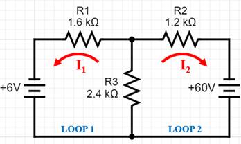
Using KVL in loop 1,
Using KVL in loop 2,
From equation (1), we can write I2as ,
Substitute this expression for I2in equation (2),
The negative sign indicates that the direction of current is different from that assumed at the start.
Substitute the value of I1 in equation (3).
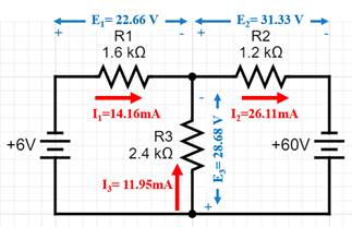
CurrentI3 is the sum of currents I1 and I2
The voltage drops are obtained by using Ohm’s Law,
The results are summarized in the figure below,
Want to see more full solutions like this?
Chapter 9 Solutions
Delmar's Standard Textbook of Electricity (MindTap Course List)


- Solve without using alarrow_forwardDon't use ai to answer I will report you answerarrow_forwardThe values of the elements in the circuit given in the figure are given below. Find the maximum average power that can be transferred to the ZL load. Vg=5cos(10000t) VoltR=38 kilo ohmC=35 nano faradL=150 milli henryarrow_forward
- Prelab Information 1. Laboratory Preliminary Discussion Second-order RC Circuit Analysis The second-order RC circuit shown in figure 1 below represents all voltages and impedances as functions of the complex variable, s. Note, of course, that the impedances associated with Rs, R₁, and R2 are constant independent of frequency, so the 's' notation is omitted. Again, one of the advantages of s-domain analysis is that we can apply all of the circuit analysis techniques learned for AC and DC circuits. To generate the s-domain expression for the output voltage, Vout(s) = Vc2(s), for the circuit shown in figure 1, we can apply voltage division in the s-domain as shown in equation 1 below. Equation 1 will be used in the prelab computations to find an expression for the output voltage, vc2(t), in the time domain. Note also that when we collect frequency response data for the circuit it will be operating at AC steady-state conditions for each frequency tested. Note that under AC steady-state…arrow_forwardDon't use ai to answer I will report you answerarrow_forwardThe power values of the loads in the circuit given in the figure are given below. Accordingly, which of the following is the RMS value of the Vs voltage amplitude? Load 1 (L1): the power factor is 1 and draws 13 kW of power,Load 2 (L2): draws 1 kVA at a forward power factor of 0.6,Load 3 (L3): draws 4 kW of average power and gives 3 kVAR of reactive power.arrow_forward
- The values of the elements in the circuit given in the figure are given below. Find the average power value on the R2 resistor. (Hint: First find the current of the R2 resistor with the loop current method. Four mutual inductance effect expressions should be added to each of the two loop equations.) Vs=238 voltsR1=13 ohmsR2=15 ohmsarrow_forwardDon't use ai to answer I will report you answerarrow_forwardA transformer bank is composed of three single-phase transformers of10kVA, 20kV/200V; copper losses are 100 W and core lossesthey are 50 W. The bank is connected in Delta on the high voltage side and in star on the sidethe low-voltage side. A. What are the values of voltages B.What are the values of currents C. losses in the core and losses in copper. D. nominal power of the transformer bank.Solve by one of the experts, not using artificial intelligencearrow_forward
 EBK ELECTRICAL WIRING RESIDENTIALElectrical EngineeringISBN:9781337516549Author:SimmonsPublisher:CENGAGE LEARNING - CONSIGNMENT
 Electricity for Refrigeration, Heating, and Air C...Mechanical EngineeringISBN:9781337399128Author:Russell E. SmithPublisher:Cengage Learning