
Concept explainers
Find the hydraulic uplift force at the base of the hydraulic structure per meter length.
Answer to Problem 8.5P
The hydraulic uplift force at the base of the hydraulic structure per meter length is
Explanation of Solution
Given information:
The hydraulic conductivity of the permeable soil layer k is
The head difference between the upstream and downstream H is 10 m.
The height of the water level
The depth of permeable layer up to the tip of the hydraulic structure D is 1.67 m.
The depth of permeable layer
Calculation:
Draw the free body diagram of the flow net for the given values as in Figure 1.
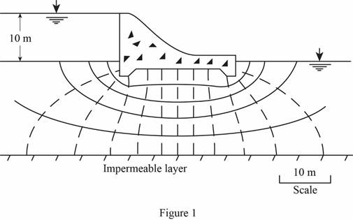
Determine the head loss for each drop using the relation.
Here,
Refer Figure 1.
The number of potential drop
Substitute 10 m for H and 12 for
Determine the pressure head at D using the relation.
Here, flow dis is the flow net distance.
Substitute 10 m for H, 3.34 m for
Determine the pressure head at E using the relation.
Substitute 10 m for H, 3.34 m for
Determine the pressure head at F using the relation.
Substitute 10 m for H, 1.67 m for D, 3.5 m for flow dis, and 0.833 for
Determine the pressure head at G using the relation.
Substitute 10 m for H, 1.67 m for D, 8.5 m for flow dis, and 0.833 for
Determine the pressure head at H using the relation.
Substitute 10 m for H, 3.34 m for
Determine the pressure head at I using the relation.
Substitute 10 m for H, 3.34 m for
Determine the hydraulic uplift force at the base of the hydraulic structure per meter length using the relation.
Here,
Take unit weight of water
Substitute
Draw the pressure head diagram as in Figure 2.
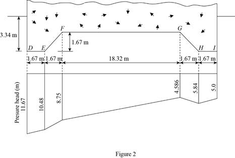
Therefore, the hydraulic uplift force at the base of the hydraulic structure per meter length is
Want to see more full solutions like this?


- For the frame shown below, determine the vertical displacement at C. Assume that flexural rigidities AB and BC segments are EI and 2EI, respectively. Use the method of virtual work and show all working.arrow_forwardDETERMINE THE BEARINGS OF THE POLYGON/TRAVERSEarrow_forward54 7h de зк +F B + 8 8 Ө 6 A=Sin² E=290ooks for diagonal members A= 30.25in² E = 1800 ksi for hoizontal & Vertical members For Primary Structure revive roller@c, make Da roller and cut BF For redundant structures Redundant " " 2 склес しん Ik @D 3 14 @ BF しん ↑arrow_forward
- A3.2- The 4.5m long cantilever beam is subjected to the specified uniformly distributed dead load 7.0 kN/m (including self-weight) and to the specified uniformly distributed live load 8.0 kN/m. The beam is made of normal density concrete containing maximum 20mm aggregate size with f'c = 25 MPa. Design the shear reinforcement for the beam using U-stirrups and fy = 400 MPa. Figure 2 WDL = 7.0 kN/m WLL=8.0 kN/m 4.5 m 450 mm' 380 mm *250 mm 3-30M Cross-sectionarrow_forwardA3.1- A simply supported beam is subjected to factored concentrated load of 400 kN at mid-span. The beam has a 10m span and a rectangular cross-section with bw = 350mm, effective depth d = 520mm, and total height h = 620mm. a) Ignor the self-weight of the beam and design the required shear reinforcement for the beam. Use 10M U-stirrups. b) Sketch the beam elevation and show the stirrups. Given: The beam is reinforced with 5-25M longitudinal bars f'c = 30 MPa fy = 400 MPa Maximum aggregate size: 20mm Figure 1 P= 400 kN k 5.0 m + 5.0 m 620 mm 520 mm 350 mm + Cross-sectionarrow_forward+ 54 7h de зк +F 8 B 8 Ө 6 For Primary Structure remove and cut BF For redundant structures Redundant " " 2 склес しん Ik @D 3 14 @ BF しん ↑ A=Sin² E=290ooks for diagonal members A= 30.25in² E = 1800 ksi for hoizontal & Vertical members roller@G, make Da rollerarrow_forward
- An urban freeway is to be designed using the following information. AADT = 52,600 veh/day K (proportion of AADT occurring during the peak hour): D (proportion of peak hour traffic traveling in the peak direction): Trucks: 0.11 0.65 8% of peak hour volume PHF = 0.94 Lane width: Shoulder width: Total ramp density: Terrain: 12 ft 10 ft 0.5 interchange/mile; all interchanges are to be cloverleaf interchanges rolling Determine the number of lanes in the peak direction required to provide LOS C. (Assume commuter traffic and assume no RVs.) lanes Show all calculations required. (Calculate your answers for the peak direction only. Enter fy the peak hour volume in veh/h, the free flow speed in mi/h, the demand flow rate in pc/h/In, the mean speed in mi/h, and the density in pc/mi/In.) fHV peak hour volume free flow speed demand flow rate mean speed veh/h mi/h pc/h/In mi/h density pc/mi/Inarrow_forwardThe beam shown in the figure below is a W16 × 31 of A992 steel and has continuous lateral support. The two concentrated loads are service live loads. Neglect the weight of the beam and determine whether the beam is adequate. Suppose that P = 56 k. For W16 x 31: d=15.9 in., t = 0.275 in., h/t = 51.6, and M = M₁ = 203 ft-kip, M/ P P = = Mp/ =135 ft-kip. 6' W16 x 31 a. Use LRFD. Calculate the required moment strength, the allowable shear strength, and the maximum shear. (Express your answers to three significant figures.) = Mu QvVn Vu = = Beam is -Select- b. Use ASD. ft-kip kips kips Calculate the required moment strength, the allowable shear strength, and the maximum shear. (Express your answers to three significant figures.) Ma = Vn/b Va = = Beam is -Select- ft-kip kips kipsarrow_forward***Please answer all parts. They are part of a single question and not different questions altogether. I will like the solution as well. Thank you!arrow_forward
- Consider the geometric and traffic characteristics shown below. Approach (Width) Peak hour Approach Volumes: Left Turn Through Movement Right Turn Conflicting Pedestrian Volumes PHF For the following saturation flows: North (56 ft) South (56 ft) East (68 ft) West (68 ft) 165 105 200 166 442 395 585 538 162 157 191 200 900 1,200 1,200 900 0.95 0.95 0.95 0.95 Through lanes: 1,600 veh/h/in Through-right lanes: 1,400 veh/h/in Left lanes: 1,000 veh/h/in Left-through lanes: 1,200 veh/h/in Left-through-right lanes: 1,100 veh/h/in The total cycle length was 277 s. Now assume the saturation flow rates are 10% higher, that is, assume the following saturation flow rates: Through lanes: Through-right lanes: Left lanes: Left-through lanes: Left-through-right lanes: 1,760 veh/h/in 1,540 veh/h/in 1,100 veh/h/in 1,320 veh/h/in 1,210 veh/h/in Determine a suitable signal phasing system and phase lengths (in s) for the intersection using the Webster method. (Enter the sum of green and yellow times for…arrow_forwardDetermine the minimum of the appropriate yellow interval (Y . approach speed limit: 45 mi/h approach grade: 3.2% downgrade assumed perception-reaction time: 1.0 sec assumed deceleration rate: 11.2 ft/sec² assumed average vehicle length: 20 ft width of intersection to be crossed: 56 ft min' in s) for a signal phase under the following conditions.arrow_forwardCompute the nominal shear strength of an M10 × 7.5 of A572 Grade 60 steel (Fy = 60 ksi). For M10 × 7.5: d = 9.99 in., tw = 0.13 in., h/tw Vn = x kips = 71.arrow_forward
 Fundamentals of Geotechnical Engineering (MindTap...Civil EngineeringISBN:9781305635180Author:Braja M. Das, Nagaratnam SivakuganPublisher:Cengage Learning
 Principles of Foundation Engineering (MindTap Cou...Civil EngineeringISBN:9781337705028Author:Braja M. Das, Nagaratnam SivakuganPublisher:Cengage Learning
 Principles of Geotechnical Engineering (MindTap C...Civil EngineeringISBN:9781305970939Author:Braja M. Das, Khaled SobhanPublisher:Cengage Learning
 Principles of Foundation Engineering (MindTap Cou...Civil EngineeringISBN:9781305081550Author:Braja M. DasPublisher:Cengage Learning