
Concept explainers
Videos
Refer to the circuit shown in Figure 8-25 to solve the following problems.
Find the unknown values in the circuit if the total current is 0.8 A and the resistors have the following values:
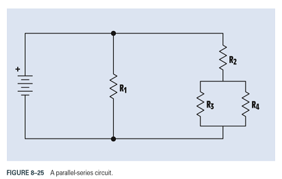
FIGURE 8-25 A parallel-series circuit.

Trending nowThis is a popular solution!

Chapter 8 Solutions
TEXTBOOK OF ELECTRICITY W/MINDTAP >BI<


- Please solutionarrow_forwardUse data sheet B on page 383 to draw the wiring diagram. Note: use only the number of contacts required. First 1. Wire the motor to operate in forward and reverse at 115 VAC.arrow_forwardB:A 20 MVA transformer which may be called upon to operate at 30% overload, feeds 11 KV busbars through a circuit breaker: other circuit breakers supply outgoing feeders. The transformer circuit breaker is equipped with 1000/5 A CTS and the feeder circuit breakers with 400/5 A CTS and all sets of CTs feed induction type over current relays. The relays on the feeder circuits breakers have a 125% plug setting, and 0.3 time setting. If 3 ph fault current of 5000 A flows from the transformer to one of the feeders, find the operating time of the feeder relay, the minimum plug setting of the transformer relay and its time setting assuming a discrimination time margin of 0.5 sec. Relays having the following characteristics for TMS=1 PSM T in sec. 2 3.6 5 10 15 20 10 6 3.9 2.8 2.2 2.1arrow_forward
- 10.34 Determine the power readings of the two wattmetersshown in the circuit of Fig. P10.34 given that ZY = (15− j5) Warrow_forward10.29 A 208-V (rms) balanced three-phase source supports twoloads connected in parallel. Each load is itself a balanced threephaseload. Determine the line current, given that load 1 is 12 kVAat pf 1 = 0.7 leading and load 2 is 18 kVA at pf 2 = 0.9 lagging.arrow_forward10.31 A 240-V (rms), 60-Hz Y-source is connected to a balancedthree-phase Y-load by four wires, one of which is the neutral wire.If the load is 400 kVA at pf old = 0.6 lagging, what size capacitorsshould be added to change the power factor to pf new = 0.95lagging?arrow_forward
- Cable A Cable A is a coaxial cable of constant cross section. The metal regions are shaded in grey and are made of copper. The solid central wire has radius a = 5mm, the outer tube inner radius b = 20mm and thickness t = 5mm. The dielectric spacer is Teflon, of relative permittivity &r = 2.1 and breakdown strength 350kV/cm. A potential difference of 1kV is applied across the conductors, with centre conductor positive and outer conductor earthed. Before undertaking any COMSOL simulations we'll first perform some theoretical analysis of Cable A based on the EN2076 lectures, to make sense of the simulations. Calculate the radial electric field of cable A at radial positions r b. Also calculate the maximum operating voltage of cable A, assuming a safety margin of ×2, and indicate where on the cable's cross section dielectric breakdown is most likely to occur.arrow_forward: For the gravity concrete dam shown in the figure, the following data are available: The factor of safety against sliding (F.S sliding)=1.2 Unit weight of concrete (Yconc)=24 KN/m³ - Neglect( Wave pressure, silt pressure, ice force and earth quake force) μ=0.65, (Ywater) = 9.81 KN/m³ Find factor of safety against overturning (F.S overturning) 6m3 80m Smarrow_forwardI need help checking if its correct -E1 + VR1 + VR4 – E2 + VR3 = 0 -------> Loop 1 (a) R1(I1) + R4(I1 – I2) + R3(I1) = E1 + E2 ------> Loop 1 (b) R1(I1) + R4(I1) - R4(I2) + R3(I1) = E1 + E2 ------> Loop 1 (c) (R1 + R3 + R4) (I1) - R4(I2) = E1 + E2 ------> Loop 1 (d) Now that we have loop 1 equation will procced on finding the equation of I2 current loop. However, a reminder that because we are going in a clockwise direction, it goes against the direction of the current. As such we will get an equation for the matrix that will be: E2 – VR4 – VR2 + E3 = 0 ------> Loop 2 (a) -R4(I2 – I1) -R2(I2) = -E2 – E3 ------> Loop 2 (b) -R4(I2) + R4(I1) - R2(I2) = -E2 – E3 -----> Loop 2 (c) R4(I1) – (R4 + R2)(I2) = -E2 – E3 -----> Loop 2 (d) These two equations will be implemented to the matrix formula I = inv(A) * b R11 R12 (R1 + R3 + R4) -R4 -R4 R4 + R2arrow_forward
 Delmar's Standard Textbook Of ElectricityElectrical EngineeringISBN:9781337900348Author:Stephen L. HermanPublisher:Cengage Learning