
(a)
Find the vertical displacement of joint C.
(a)
Answer to Problem 4P
The vertical deflection at joint C
Explanation of Solution
Given information:
Area of members AB, BC, and CD are
The value of E is
Procedure to find the deflection of truss by virtual work method is shown below.
For Real system: If the deflection of truss is determined by the external loads, then apply method of joints or method of sections to find the real axial forces (F) in all the members of the truss.
For virtual system: Remove all given real loads, apply a unit load at the joint where is deflection is required and also in the direction of desired deflection. Use method of joints or method of sections to find the virtual axial forces
Finally use the desired deflection equation.
Apply the sign conventions for calculating reactions, forces and moments using the three equations of equilibrium as shown below.
For summation of forces along x-direction is equal to zero
For summation of forces along y-direction is equal to zero
For summation of moment about a point is equal to zero
Method of joints:
The negative value of force in any member indicates compression (C) and the positive value of force in any member indicates tension (T).
Condition for zero force members:
If only two non-collinear members are connected to a joint that has no external loads or reactions applied to it, then the force in both the members is zero.
If three members, two of which are collinear are connected to a joint that has no external loads or reactions applied to it, then the force in non-collinear member is zero.
Calculation:
Find the bar forces
Let
Let
Find the reactions at the supports using equilibrium equations:
Summation of moments about A is equal to 0.
Summation of forces along y-direction is equal to 0.
Summation of forces along x-direction is equal to 0.
Find the member forces using method of joints:
Apply equilibrium equation to the joint A:
Apply equilibrium equation to the joint D:
Apply equilibrium equation to the joint B:
Apply equilibrium equation to the joint C:
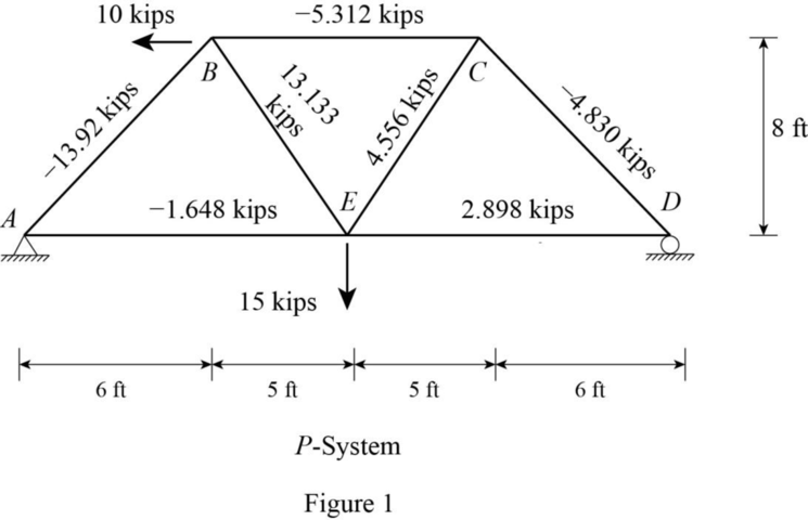
Sketch the bar forces produced by the P-system as shown in Figure 1.
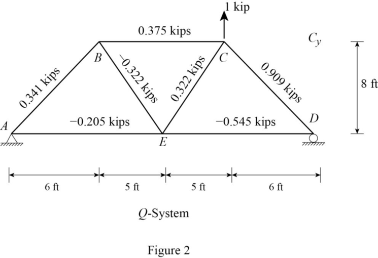
Consider a dummy load of 1 kN directed vertically at joint C with the bar forces
Find the reactions at the supports using equilibrium equations:
Summation of moments about A is equal to 0.
Summation of forces along y-direction is equal to 0.
Summation of forces along x-direction is equal to 0.
Find the member forces using method of joints:
Apply equilibrium equation to the joint A:
Apply equilibrium equation to the joint D:
Apply equilibrium equation to the joint B:
Apply equilibrium equation to the joint C:
Sketch the bar forces
Refer Table 1 for vertical displacement of joint C.
(b)
Find the horizontal displacement of joint C.
(b)
Answer to Problem 4P
The horizontal deflection at joint C
Explanation of Solution
Given information:
Area of members AB, BC, and CD are
Calculation:
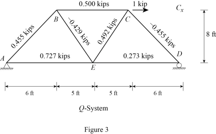
Consider a dummy load of 1 kN directed horizontally at joint C with the bar forces
Find the reactions at the supports using equilibrium equations:
Summation of moments about A is equal to 0.
Summation of forces along y-direction is equal to 0.
Summation of forces along x-direction is equal to 0.
Find the member forces using method of joints:
Apply equilibrium equation to the joint A:
Apply equilibrium equation to the joint D:
Apply equilibrium equation to the joint B:
Apply equilibrium equation to the joint C:
Sketch the bar forces
Refer Table 1 for horizontal displacement of joint C.
(c)
Find the horizontal displacement of joint D.
(c)
Answer to Problem 4P
The horizontal deflection at joint D
Explanation of Solution
Given information:
Area of members AB, BC, and CD are
Calculation:
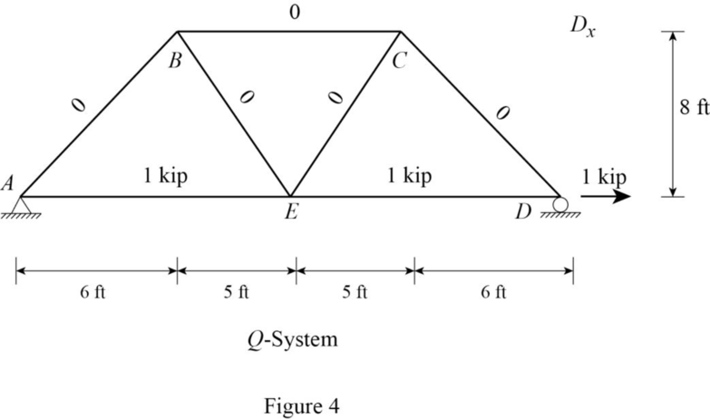
Consider a dummy load of 1 kN directed horizontally at joint D with the bar forces
Find the reactions at the supports using equilibrium equations:
Summation of moments about A is equal to 0.
Summation of forces along y-direction is equal to 0.
Summation of forces along x-direction is equal to 0.
Find the member forces using method of joints:
Apply equilibrium equation to the joint A:
Apply equilibrium equation to the joint D:
The force in the member AB, BE, EC, BC, and CD are zero as it satisfies zero force member condition.
Sketch the bar forces
Find the vertical deflection at joint C
Find the horizontal deflection at joint C
Find the product of
| Bar |
A |
L | ||||||||
| AB | 1 | 10 | 0.455 | 0.341 | 0 | 0 | ||||
| BC | 1 | 10 | 0.500 | 0.375 | 0 | 0 | ||||
| CD | 1 | 10 | 0.909 | 0 | 0.026 | 0 | ||||
| DE | 0.25 | 11 | 2.898 | 0.273 | 1 | 0.042 | 0.153 | |||
| EA | 0.25 | 11 | 0.727 | 1 | 0.018 | |||||
| EB | 0.25 | 9 | 13.133 | 0 | 0 | |||||
| EC | 0.25 | 9 | 4.556 | 0.429 | 0 | 0.066 | 0 | |||
Refer Table 1.
The vertical deflection at joint C
The horizontal deflection at joint C
The horizontal deflection at joint D
Want to see more full solutions like this?
Chapter 8 Solutions
UCD FUND OF STRUCTURAL ANALYSIS 5E

- 9.16 Two vertical parallel plates are spaced 0.012 ft apart. If the pressure decreases at a rate of 100 psf/ft in the vertical z direction in the fluid between the plates, what is the maximum fluid velocity in the Z direction? The fluid has a viscosity of 10-3 Ibf s/ft² and a specific gravity of 0.80. .arrow_forwardPlease explain steps using software.arrow_forwardPlease explain steps for using softwarearrow_forward
- Design the reinforced masonry beam in the wall shown below. The wall is to be constructed of fully grouted hollow concrete masonry units in running bond. It is to carry its own weight plus a superimposed dead load of 2.5 kips/ft and a live load of 0.8 kip/ft. Determine the width of the masonry units (by trials), and the amounts of the longitudinal and shear reinforcement required using the strength design method of TMS 402-22. Show the layout of the reinforcements with diagrams. Use fm = 2,000 psi, Grade 60(60 ksi) steel, and Type S Portland cement mortar. Assume that the centroid of the bottom rebar is 3 inches from the bottom face of the beam. ( you may assume that the unit weight of fully grouted concrete masonry is 125 lbs per cubic foot.)arrow_forward6. The easiest method to solve the beam shown in question number 14 is A. Force method B. Slope deflection method C. Moment distribution method D. Virtual work method E. Stiffness matrix method 17. The value of 8 caused by applying CW moment at A equal to 18. A. ML/2E1 B. ML/3E1 C. ML/4E1 D. ML/6EI E. None of the above For the beam shown below, the moment at A kN.m CCW. Assume P= 8 kN equals to ........ A. 20 B. 22.5 C. 25 D. 27.5 E. 30 M L A unlocked joint end pin P P P B A 1m 1m 2m 2m 19. The analysis of indeterminate non sway frames using moment distribution method does not need..... A. Finding stiffness factors of members B. Finding fix end moments C. Using compatibility equations D. Removing redundants E. Cand D 0. The frame shown is kinematically 6 kN/m indeterminate to ................ degree. A, C and D are fixed. E and B are pinned. A. First B. Second C. Third D. Fourth E. None of the above 6 m Sm 7 marrow_forward1. The moment at A using slope deflection method equals to 10 kN ..... kN. m CCW. A. 2.5 B. 5 C. 7.5 D. 10 E. None of the above 2m 2m B 10 kN + 2m + 2m 2. To solve the beam shown using slope deflection method,. ...... unknowns (s) 25 kN 15 kN/m should be selected. A. One B. Two fix C. Three D. Four E. None of the above magnitude of the rotation at B for the me shown using slope deflection method quals to El constant. A. -162/EI B. -162 El C. 40/El D. -40 El E. 0.3 radian B A 3 m 3 m -4 m- 4k/ft roller A fix 18 ft. To solve the beam shown using slope deflection method, should be fix selected as equilibrium equation (s). A. MAB+MBA = 0 B. MAB + MBA 0 and MBC=0 C. MBA+MBC = 0 D. MBA+MBC = 0 and MCB=0 E. None of the above B fix fix 9ft 20 kN/m 80 EN pin 9 m 3 m rollerarrow_forward
- Solvearrow_forward5. The number of unknowns for the frame shown using slope deflection method is... Assume A, B and D are fixed and interior hinge at C A. Two B. Four C. Six D. Eight E. None of the above 10 kN B Qc 4m A 3m + + 3m 3m 6. 7. The slope-deflection method was originally developed by Heinrich Manderla and Otto Mohr for the purpose of studying. A. secondary stresses in trusses B. secondary stresses in beams and frames C. Indeterminate beams and frames analysis D. Determinate beams and frames analysis E. None of the above In structures that have non-parallel end members, the displacement of the members will be..... A. Similar B. Different C. Proportional D. Zero E. None of the above. 8. The magnitude of the fix end moment at A 4k/ft using slope deflection method equals to pin exfix ...........k. ft. A. 25 B. -25 C. 40 D. -40 E. None of the above. A roller 15 ft- 12 f The magnitude of MBC for the frame shown in question number 3 using slope deflection method equals Assume El constant for all…arrow_forwardQ2. An isotropic rectangular slab (6 x 8) m is fixed at 3- edges and free at one edge as shown below. The reinforcement provides a positive yield moment of (10) kN.m/m and along the fixed edge a negative yield moment (m) of (14) kN.m/ m. Determine the collapse load if the slab carries a u.d.L. of (w) kN/m² including the slab own weight. W free C Gm fixed 8 m darrow_forward
- Reinforced Concrete Design 4 Second Monthly Exam 15/4/2025 Q1. A double T-concrete beam is prestressed with 2- tendons each of cross-sectional area of (600) mm² as shown below. Determine the allowable service load. Given: Span = 12 m, fse=1400 N/mm², fé= 50 N/mm², Ct = 163 mm, Cb =437 mm, I=7586 x 10 mm*. 10 KN/M * 25.00 x-500x 1500 +500 +100 163 不 -A 500 12m + 437 += 50 1 150 150 600mm 600mmarrow_forward5-18 Determine the maximum service live load that the column shown in Figure P5-18 can support if the live load is twice the dead load. (Lc)x = KxLx = 24 ft, (Lc)y = KyLy = 16 ft = 36 ksi. Solve by LRFD and ASD methods. and Fy Figure P5-18 C6×13 C6×13 PLX14X4arrow_forwardPlease answer the question in the picture, show all of you work in pictures and handwritten.arrow_forward

 Structural Analysis (10th Edition)Civil EngineeringISBN:9780134610672Author:Russell C. HibbelerPublisher:PEARSON
 Principles of Foundation Engineering (MindTap Cou...Civil EngineeringISBN:9781337705028Author:Braja M. Das, Nagaratnam SivakuganPublisher:Cengage Learning
 Fundamentals of Structural AnalysisCivil EngineeringISBN:9780073398006Author:Kenneth M. Leet Emeritus, Chia-Ming Uang, Joel LanningPublisher:McGraw-Hill Education
 Traffic and Highway EngineeringCivil EngineeringISBN:9781305156241Author:Garber, Nicholas J.Publisher:Cengage Learning