
Concept explainers
Draw the influence lines for the reaction moment at support A, the vertical reactions at supports A and F and the shear and bending moment at point E.
Explanation of Solution
Calculation:
Influence line for moment at support A.
Apply a 1 kN unit moving load at a distance of x from left end C.
Sketch the free body diagram of frame as shown in Figure 1.
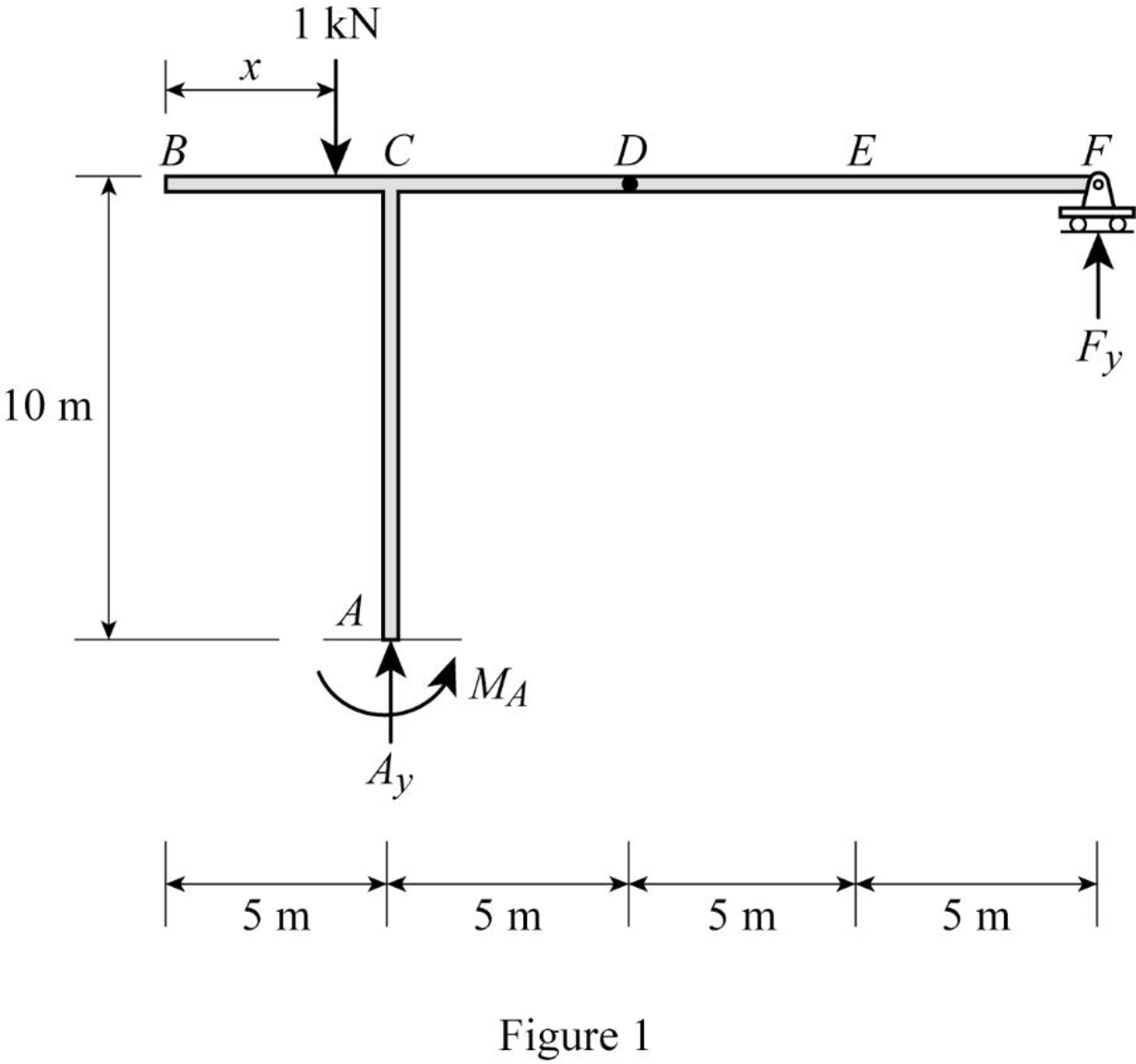
Refer Figure 1.
Apply 1 kN load just left of C
Take moment at A from B.
Consider clockwise moment as positive and anticlockwise moment as negative.
Apply 1 kN load just right of C and just left of D
Take moment at A from D.
Apply 1 kN load just right of D and just right of F
Take moment at A from F.
Thus, the equation of moment at A as follows,
Find the influence line ordinate of
Substitute 0 for
Find the influence line ordinate of
The vertical reaction at F is 1 kN when 1 kN applied at F.
Substitute 20 m for
Thus, the influence line ordinate of
Similarly calculate the influence line ordinate of
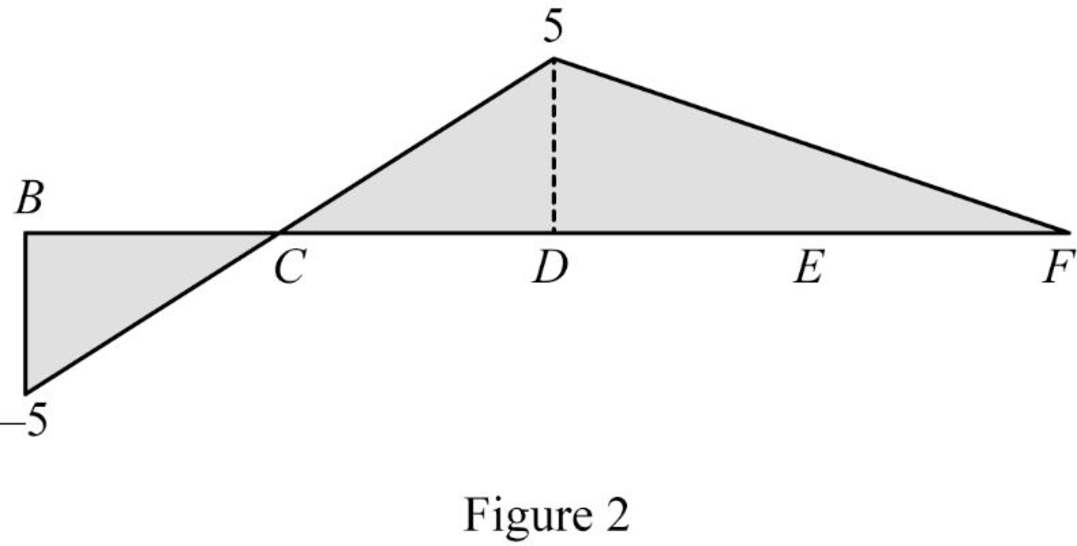
| x (m) | Points | Influence line ordinate of |
| 0 | B | ‑5 |
| 5 | C | 0 |
| 10 | D | 5 |
| 20 | F | 0 |
Sketch the influence line diagram for the moment at support A using Table 1 as shown in Figure 2.
Influence line for vertical reaction at support F.
Apply a 1 kN unit moving load at a distance of x from left end C.
Refer Figure 1.
Find the vertical support reaction
Apply 1 kN load just left of D
Consider section DF.
Consider moment equilibrium at point D.
Consider clockwise moment as positive and anticlockwise moment as negative
Apply 1 kN load just right of D
Consider section DF.
Consider moment equilibrium at point D.
Consider clockwise moment as positive and anticlockwise moment as negative
Thus, the equation of vertical support reaction at F as follows,
Find the influence line ordinate of
Substitute 20 for
Thus, the influence line ordinate of
Similarly calculate the influence line ordinate of
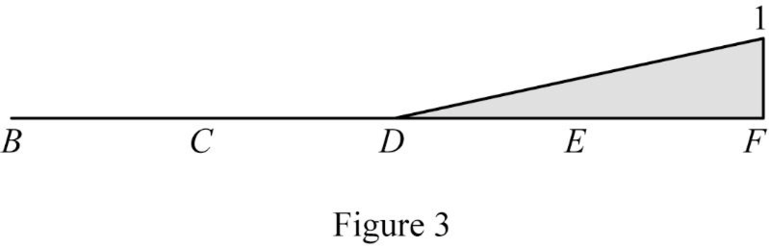
| x (m) | Points | Influence line ordinate of |
| 0 | B | 0 |
| 5 | C | 0 |
| 10 | D | 0 |
| 15 | E | 0.5 |
| 20 | F | 1 |
Sketch the influence line diagram for the vertical reaction at support F using Table 2 as shown in Figure 3.
Influence line for vertical reaction at support A.
Apply a 1 kN unit moving load at a distance of x from left end C.
Refer Figure 1.
Apply vertical equilibrium in the system.
Consider upward force as positive and downward force as negative.
Find the equation of vertical support reaction
Substitute 0 for
Find the equation of vertical support reaction
Substitute
Thus, the equation of vertical support reaction at A as follows,
Find the influence line ordinate of
Substitute 20 m for
Thus, the influence line ordinate of
Similarly calculate the influence line ordinate of
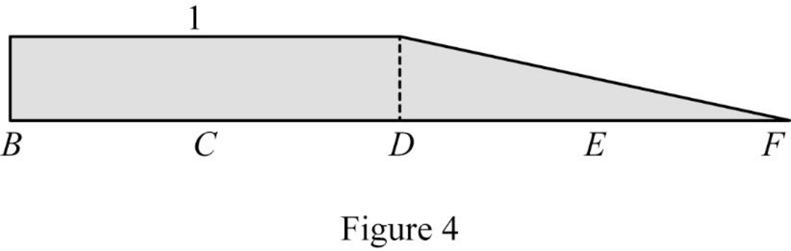
| x (m) | Points | Influence line ordinate of |
| 0 | B | 1 |
| 5 | C | 1 |
| 10 | D | 1 |
| 15 | E | 0.5 |
| 20 | F | 0 |
Sketch the influence line diagram for the vertical reaction at support A using Table 3 as shown in Figure 4.
Influence line for shear at point E.
Sketch the free body diagram of the section BD as shown in Figure 5.
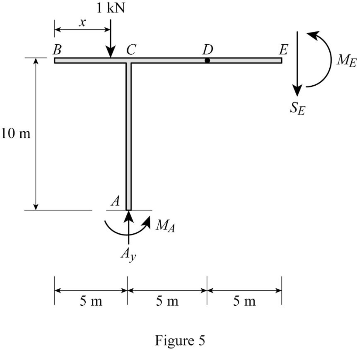
Refer Figure 5.
Apply equilibrium equation of forces.
Consider upward force as positive
Find the equation of shear force at E of portion BD
Substitute
Find the equation of shear force at E of portion DE
Substitute
Find the equation of shear force at E of portion EF
Sketch the free body diagram of the section EF as shown in Figure 6.
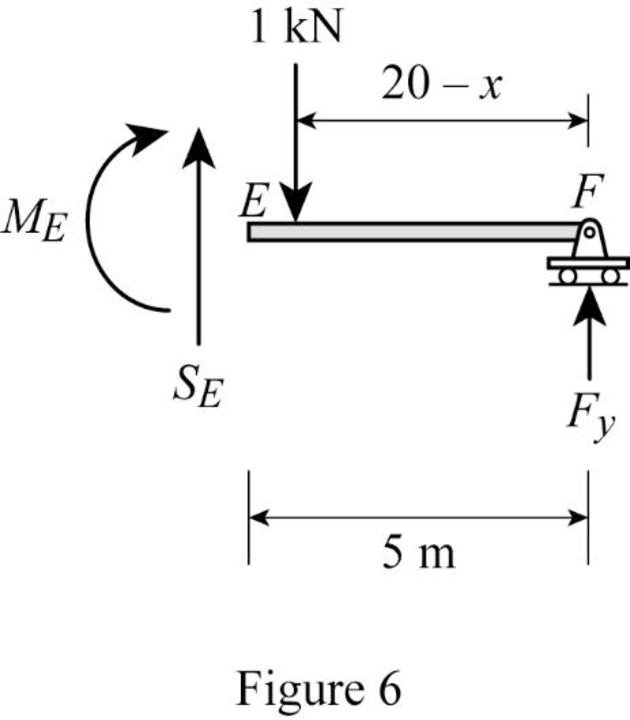
Refer Figure 6.
Apply equilibrium equation of forces.
Consider upward force as positive
Substitute
Thus, the equations of the influence line for
Find the influence line ordinate of
Substitute 15 m for
Thus, the influence line ordinate of
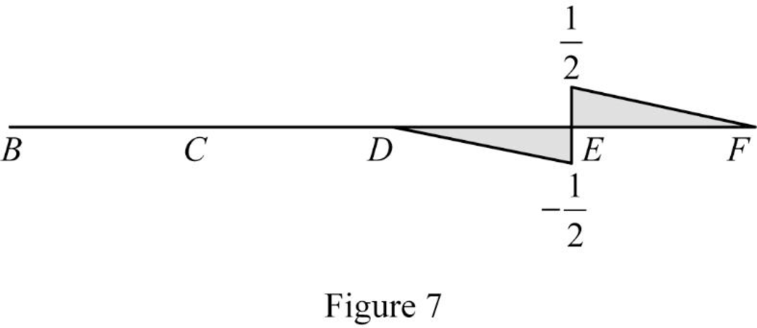
Find the shear force of
| x (m) | Points | Influence line ordinate of |
| 0 | B | 0 |
| 5 | 0 | |
| 10 | 0 | |
| 15 | ||
| 15 | ||
| 20 | F | 0 |
Draw the influence lines for the shear force at point E using Table 4 as shown in Figure 7.
Influence line for moment at point E.
Refer Figure 5.
Consider section BE.
Consider clockwise moment as positive and anticlockwise moment as negative.
Take moment at E.
Find the equation of moment at E of portion BE.
Find the equation of moment at E of portion BD
Substitute
Find the equation of moment at E of portion DE
Substitute
Substitute
Refer Figure 6.
Consider section EF.
Find the equation of moment at E of portion EF
Consider clockwise moment as positive and anticlockwise moment as negative.
Take moment at E.
Find the equation of moment at E of portion EF.
Substitute
Thus, the equations of the influence line for
Find the influence line ordinate of
Substitute 15 m for
Thus, the influence line ordinate of
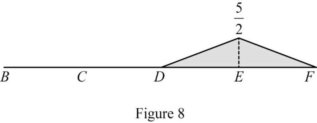
Find the moment at various points of x using the Equations (5) and (6) and summarize the value as in Table 5.
| x (m) | Points | Influence line ordinate of |
| 0 | B | 0 |
| 5 | C | 0 |
| 10 | D | 0 |
| 15 | E | |
| 20 | F | 0 |
Draw the influence lines for the moment at point E using Table 5 as shown in Figure 8.
Therefore, the influence lines for the vertical reactions at supports A and F and the influence lines for the shear and bending moment at point E are drawn.
Want to see more full solutions like this?
Chapter 8 Solutions
EBK STRUCTURAL ANALYSIS


- Show step by step solutionarrow_forwardDraw the shear and the moment diagrams for each of the frames below. If the frame is statically indeterminate the reactions have been provided. Problem 1 (Assume pin connections at A, B and C). 30 kN 2 m 5 m 30 kN/m B 60 kN 2 m 2 m A 22 CO Carrow_forwardThis is an old exam practice question. The answer key says the answer is Pmax = 52.8kN but I am confused how they got that.arrow_forward
- F12-45. Car A is traveling with a constant speed of 80 km/h due north, while car B is traveling with a constant speed of 100 km/h due east. Determine the velocity of car B relative to car A. pload Choose a File Question 5 VA - WB VBA V100 111413 + *12-164. The car travels along the circular curve of radius r = 100 ft with a constant speed of v = 30 ft/s. Determine the angular rate of rotation è of the radial liner and the magnitude of the car's acceleration. Probs. 12-163/164 pload Choose a File r = 400 ft 20 ptsarrow_forwardPlease show step by step how to solve this and show formulararrow_forwardPlease solve this question step by step with dia gramarrow_forward
- Use the second picture to answer the question, Thank you so much for your help!arrow_forwardP6.16 A compound shaft (Figure P6.16) consists of a titanium alloy [G= 6,200 ksi] tube (1) and a solid stainless steel [G= 11,500 ksi] shaft (2). Tube (1) has a length L₁ = 40 in., an outside diameter D₁ = 1.75 in., and a wall thickness t₁ = 0.125 in. Shaft (2) has a length 42 = 50 in. and a diameter d₂ = 1.25 in. If an external torque TB = 580 lb ft acts at pulley B in the direction shown, calculate the torque Tcrequired at pulley C so that the rotation angle of pulley Crelative to A is zero. B Te (2) TB (1) FIGURE P6.16arrow_forward7.43 Neglecting head losses, determine what horsepower the pump must deliver to produce the flow as shown. Here, the elevations at points A, B, C, and D are 124 ft, 161 ft, 110 ft, and 90 ft, respectively. The nozzle area is 0.10 ft². B Nozzle Water C Problem 7.43arrow_forward
