
Concept explainers
Videos
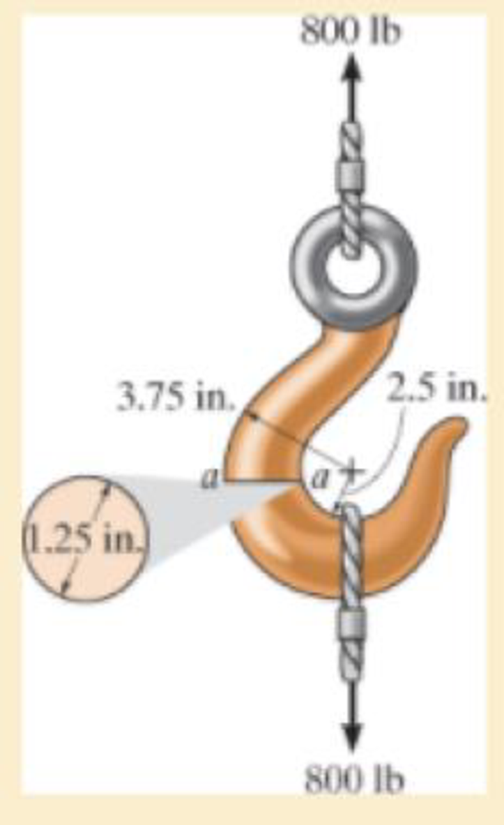
If it supports a cable loading of 800 lb, determine the maximum normal stress at section a–a and sketch the stress distribution acting over the cross section. Use the curved-beam formula to calculate the bending stress.
The maximum tensile stress
The maximum compressive stress
To sketch:
The stress distribution over the cross section.
Answer to Problem 1RP
The maximum tensile stress
The maximum compressive stress
Explanation of Solution
Given information:
The force in the cable is 800 lb.
Diameter of the circular is 1.25 in.
Calculation:
Expression to find the location of neutral
Here, R is the location of neutral axis, A is the cross sectional area of the member, r is the arbitrary position, and
Determine the radius
Here, d is the diameter of the circular cross section.
Substitute 1.25 in. for d in Equation (2).
Determine the area
Here, r is the radius of the circular cross section.
Substitute 0.625 in. for r in Equation (3).
Determine the value of
Here, c is the radius of cross section and
Find the distance measured from the center of curvature to the centroid of the cross section
Substitute 0.625 in. for c and 3.125 in. for
Substitute
Sketch the cross section of eye hook as shown in Figure 1.
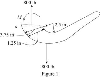
Let the moment acting at the section be M.
Express to the value of M as shown below:
Here, F is the load and R is the radius.
Determine the bending stress
Here, M is the applied moment and P is the applied load.
Substitute
Determine the maximum tensile stress
Hence, the maximum tensile stress
Determine the maximum compressive stress
Substitute
Hence, the maximum compressive stress
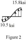
Sketch the stress distribution (tensile and compressive stress) along the cross section as shown in Figure 2.
Want to see more full solutions like this?
Chapter 8 Solutions
Mechanics of Materials


- Please do not use any AI tools to solve this question. I need a fully manual, step-by-step solution with clear explanations, as if it were done by a human tutor. No AI-generated responses, please.arrow_forwardPlease do not use any AI tools to solve this question. I need a fully manual, step-by-step solution with clear explanations, as if it were done by a human tutor. No AI-generated responses, please.arrow_forwardCE-112 please solve this problem step by step and give me the correct answerarrow_forward
- CE-112 please solve this problem step by step and give me the correct asnwerarrow_forwardthis is an old practice exam, the answer is Ax = -4, Ay = -12,Az = 32.5, Bx= 34, Bz = 5, By = 0 but how?arrow_forwardThis is an old practice exam, the answer is Ax = Az = 0, Ay = 2000, TDE = 4750, Cx = 2000, Cy = 2000, Cz = -800 but how?arrow_forward
- this is an old practice exam, the answer is Fmin = 290.5lb but howarrow_forwardThis is an exam review question. The answer is Pmin = 622.9 lb but whyarrow_forwardPlease do not use any AI tools to solve this question. I need a fully manual, step-by-step solution with clear explanations, as if it were done by a human tutor. No AI-generated responses, please.arrow_forward
- Please do not use any AI tools to solve this question. I need a fully manual, step-by-step solution with clear explanations, as if it were done by a human tutor. No AI-generated responses, please.arrow_forwardPlease do not use any AI tools to solve this question. I need a fully manual, step-by-step solution with clear explanations, as if it were done by a human tutor. No AI-generated responses, please.arrow_forwardThis is an old practice exam. Fce = 110lb and FBCD = 62 lb but whyarrow_forward
 Mechanics of Materials (MindTap Course List)Mechanical EngineeringISBN:9781337093347Author:Barry J. Goodno, James M. GerePublisher:Cengage Learning