
(a)
Find the initial current in each branch of the circuit using PSPICE.
(a)
Answer to Problem 1P
The initial current through resistor, inductor, and capacitor are
Explanation of Solution
Given data:
Refer to Figure given in the textbook.
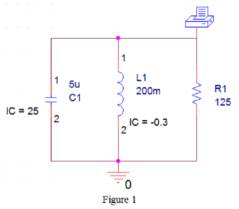
The circuit parameters are given as follows:
The initial current through the inductor
The initial voltage across the capacitor
Calculation:
As the inductor, capacitor, and resistor are connected in parallel, the initial voltage across each parallel elements are the same. Therefore,
The initial current flowing through the resistor is,
Substitute 25 for
The initial current through the inductor is,
The initial current across the capacitor is,
Substitute
Conclusion:
Thus, the initial current through resistor, inductor, and capacitor are
(b)
Find the value of
(b)
Answer to Problem 1P
The value of
Explanation of Solution
Formula used:
Write the condition for over-damped response for a parallel RLC circuit as follows:
Here,
Write the condition for under-damped response for a parallel RLC circuit as follows:
Write the condition for critically damped response for a parallel RLC circuit as follows:
Write the expression for resonant radian frequency for the given circuit as follows:
Here,
Write the expression for neper frequency for the given circuit as follows:
Here,
Write the expression of required voltage response
Write the general expression for
Write the general expression for damping constant
Write the general expression to find the value of
Calculation:
Substitute 125 for
Substitute 200 m for
Substitute 800 for
The expression (2) is satisfied. Therefore, the response is the under-damped response.
Substitute 1000 for
Substitute 25 V for
Substitute 800 for
Substitute 25 for
For various values of t in the above equation the values are calculated and tabulated in Table 1 as follows.
Table 1
| Time t in seconds | Voltage |
| 0.001 | 26.186 |
| 0.002 | 14.374 |
| 0.003 | 5.374 |
| 0.004 | 1.084 |
| 0.005 | |
| 0.006 | |
| 0.007 | |
| 0.008 |
PSPICE Circuit:
Draw the given circuit diagram in PSPICE as shown in Figure 1.
Provide the simulation settings as shown in Figure 2.
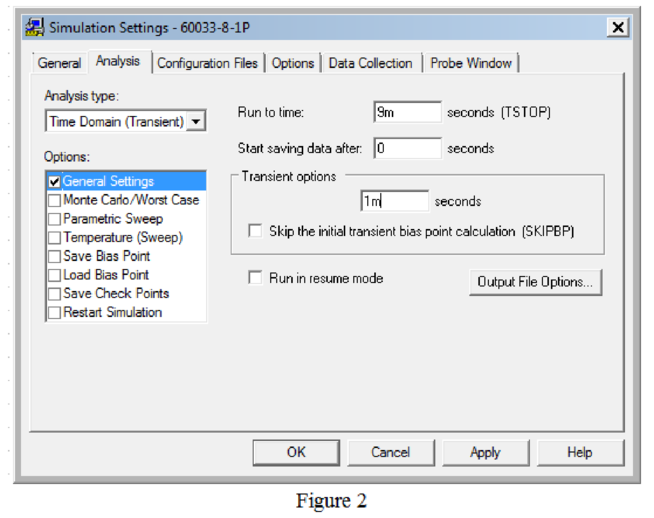
Now, run the simulation and the output will be as shown below.
Output:
TIME V(N00117)
0.000E+00 2.500E+01
1.000E-03 2.621E+01
2.000E-03 1.441E+01
3.000E-03 5.382E+00
4.000E-03 1.065E+00
5.000E-03 -2.932E-01
6.000E-03 -4.354E-01
7.000E-03 -2.627E-01
8.000E-03 -1.067E-01
9.000E-03 -2.581E-02
The simulated output and the calculated values in Table 1 are approximately equal and verified.
Conclusion:
Thus, the value of
(c)
Find the value of
(c)
Answer to Problem 1P
The value of
Explanation of Solution
Formula used:
Write the expression for
Write the expression for
Write the expression for
Calculation:
Substitute
Substitute
Substitute
Conclusion:
Thus, the value of
Want to see more full solutions like this?
Chapter 8 Solutions
EBK ELECTRIC CIRCUITS

- If C is the circle |z|=4 evaluate f f (z)dz for each of the following functions using residue. 1 f(z) = z(z²+6z+4)arrow_forwardIf C is the circle |z|=4 evaluate ff(z)dz for each of the following functions using residue. f(z) z(z²+6z+4)arrow_forwardDetermine X(w) for the given function shown in Figure (1) by applying the differentiation property of the Fourier Transform. 1 x(t) Figure (1) -2 I -1 1 2arrow_forward
- Please solve it by explaining the steps. I am trying to prepare for my exam tomorrow, so any tips and tricks to solve similar problems are highly appreciated. Plus, this is a past exam I am using to prepare.arrow_forwardPlease solve it by explaining the steps. I am trying to prepare for my exam tomorrow, so any tips and tricks to solve similar problems are highly appreciated. Plus, this is a past exam I am using to prepare.arrow_forwardPlease solve it by explaining the steps. I am trying to prepare for my exam tomorrow, so any tips and tricks to solve similar problems are highly appreciated. Plus, this is a past exam I am using to prepare.arrow_forward
- Please solve it by explaining the steps. I am trying to prepare for my exam tomorrow, so any tips and tricks to solve similar problems are highly appreciated. Plus, this is a past exam I am using to prepare.arrow_forwardPlease solve it by explaining the steps. I am trying to prepare for my exam tomorrow, so any tips and tricks to solve similar problems are highly appreciated. Plus, this is a past exam I am using to prepare.arrow_forwardPlease solve it by explaining the steps. I am trying to prepare for my exam tomorrow, so any tips and tricks to solve similar problems are highly appreciated. Plus, this is a past exam I am using to prepare.arrow_forward
- Please solve it by explaining the steps. I am trying to prepare for my exam tomorrow, so any tips and tricks to solve similar problems are highly appreciated. Plus, this is a past exam I am using to prepare.arrow_forwardPlease solve it by explaining the steps. I am trying to prepare for my exam tomorrow, so any tips and tricks to solve similar problems are highly appreciated. Plus, this is a past exam I am using to prepare.arrow_forwardPlease solve it by explaining the steps. I am trying to prepare for my exam tomorrow, so any tips and tricks to solve similar problems are highly appreciated. Plus, this is a past exam I am using to prepare.arrow_forward
 Introductory Circuit Analysis (13th Edition)Electrical EngineeringISBN:9780133923605Author:Robert L. BoylestadPublisher:PEARSON
 Delmar's Standard Textbook Of ElectricityElectrical EngineeringISBN:9781337900348Author:Stephen L. HermanPublisher:Cengage Learning
 Programmable Logic ControllersElectrical EngineeringISBN:9780073373843Author:Frank D. PetruzellaPublisher:McGraw-Hill Education
 Fundamentals of Electric CircuitsElectrical EngineeringISBN:9780078028229Author:Charles K Alexander, Matthew SadikuPublisher:McGraw-Hill Education
 Electric Circuits. (11th Edition)Electrical EngineeringISBN:9780134746968Author:James W. Nilsson, Susan RiedelPublisher:PEARSON
 Engineering ElectromagneticsElectrical EngineeringISBN:9780078028151Author:Hayt, William H. (william Hart), Jr, BUCK, John A.Publisher:Mcgraw-hill Education,