EBK VECTOR MECHANICS FOR ENGINEERS: STA
12th Edition
ISBN: 8220106797044
Author: BEER
Publisher: YUZU
expand_more
expand_more
format_list_bulleted
Concept explainers
Videos
Textbook Question
Chapter 7.3, Problem 7.73P
Using the method of Sec. 7.3, solve Prob. 7.41.
7.39 through 7.42 For the beam and loading shown, (a) draw the shear and bending-moment diagrams, (b) determine the maximum absolute values of the shear and bending moment.
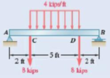
Fig. P7.41
Expert Solution & Answer
Want to see the full answer?
Check out a sample textbook solution
Students have asked these similar questions
3 kN
3 kN
1.8 kN/m
80 mm
B
300 mm
D
an
1.5 m-1.5 m--1.5 m-
PROBLEM 5.47
Using the method of Sec. 5.2, solve Prob. 5.16
PROBLEM 5.16 For the beam and loading shown, determine the
maximum normal stress due to bending on a transverse section at C.
300 mm
3 kN
3 kN
450 N-m
D
E
200 mm
300 mm
PROBLEM 5.12
Draw the shear and bending-moment diagrams for the beam and loading
shown, and determine the maximum absolute value (a) of the shear,
(b) of the bending moment.
CORRECT AND DETAILED SOLUTION WITH FBD ONLY. I WILL UPVOTE THANK YOU. CORRECT ANSWER IS ALREADY PROVIDED. I REALLY NEED FBD.
The cantilevered spandrel beam shown whose depth tapers from d1 to d2, has a constant width of 120mm. It carries a triangularly distributed end reaction.Given: d1 = 600 mm, d2 = 120 mm, L = 1 m, w = 100 kN/m1. Calculate the maximum flexural stress at the support, in kN-m.2. Determine the distance (m), from the free end, of the section with maximum flexural stress.3. Determine the maximum flexural stress in the beam, in MPa.ANSWERS: (1) 4.630 MPa; (2) 905.8688 m; (3) 4.65 MPa
Chapter 7 Solutions
EBK VECTOR MECHANICS FOR ENGINEERS: STA
Ch. 7.1 - 7.1 and 7.2 Determine the internal forces (axial...Ch. 7.1 - Prob. 7.2PCh. 7.1 - Determine the internal forces at point J when =...Ch. 7.1 - Fig. P7.3 and P7.4 7.4 Determine the internal...Ch. 7.1 - Determine the internal forces at point J when =...Ch. 7.1 - Fig. P7.5 and P7.6 7.6 Determine the internal...Ch. 7.1 - An archer aiming at a target is pulling with a...Ch. 7.1 - For the bow of Prob. 7.7, determine the magnitude...Ch. 7.1 - A semicircular rod is loaded as shown. Determine...Ch. 7.1 - A semicircular rod is loaded as shown. Determine...
Ch. 7.1 - A semicircular rod is loaded as shown. Determine...Ch. 7.1 - Fig. P7.11 and P7.12 7.12 A semicircular rod is...Ch. 7.1 - The axis of the curved member AB is a parabola...Ch. 7.1 - Knowing that the axis of the curved member AB is a...Ch. 7.1 - Knowing that the radius of each pulley is 120 mm...Ch. 7.1 - Fig. P7.15 and P7.16 7.16 Knowing that the radius...Ch. 7.1 - A 5-in.-diameter pipe is supported every 9 ft by a...Ch. 7.1 - For the frame of Prob. 7.17, determine the...Ch. 7.1 - Knowing that the radius of each pulley is 200 mm...Ch. 7.1 - Fig. P7.19 and P7.20 7.20 Knowing that the radius...Ch. 7.1 - and 7.22 A force P is applied to a bent rod that...Ch. 7.1 - and 7.22 A force P is applied to a bent rod that...Ch. 7.1 - A quarter-circular rod of weight W and uniform...Ch. 7.1 - For the rod of Prob. 7.23, determine the magnitude...Ch. 7.1 - A semicircular rod of weight W and uniform cross...Ch. 7.1 - A semicircular rod of weight W and uniform cross...Ch. 7.1 - 7.27 and 7.28 A half section of pipe rests on a...Ch. 7.1 - 7.27 and 7.28 A half section of pipe rests on a...Ch. 7.2 - 7.29 through 7.32 For the beam and loading shown,...Ch. 7.2 - 7.29 through 7.32 For the beam and loading shown,...Ch. 7.2 - 7.29 through 7.32 For the beam and loading shown,...Ch. 7.2 - 7.29 through 7.32 For the beam and loading shown,...Ch. 7.2 - 7.33 and 7.34 For the beam and loading shown, (a)...Ch. 7.2 - 7.33 and 7.34 For the beam and loading shown, (a)...Ch. 7.2 - 7.35 and 7.36 For the beam and loading shown, (a)...Ch. 7.2 - 7.35 and 7.36 For the beam and loading shown, (a)...Ch. 7.2 - 7.37 and 7.38 For the beam and loading shown, (a)...Ch. 7.2 - 7.37 and 7.38 For the beam and loading shown, (a)...Ch. 7.2 - For the beam and loading shown, (a) draw the shear...Ch. 7.2 - For the beam and loading shown, (a) draw the shear...Ch. 7.2 - For the beam and loading shown, (a) draw the shear...Ch. 7.2 - For the beam and loading shown, (a) draw the shear...Ch. 7.2 - Assuming the upward reaction of the ground on beam...Ch. 7.2 - Solve Problem 7.43 knowing that P = 3wa. PROBLEM...Ch. 7.2 - Assuming the upward reaction of the ground on beam...Ch. 7.2 - Solve Prob. 7.45 assuming that the 12-kip load has...Ch. 7.2 - Assuming the upward reaction of the ground on beam...Ch. 7.2 - Prob. 7.48PCh. 7.2 - Draw the shear and bending-moment diagrams for the...Ch. 7.2 - Draw the shear and bending-moment diagrams for the...Ch. 7.2 - Draw the shear and bending-moment diagrams for the...Ch. 7.2 - Draw the shear and bending-moment diagrams for the...Ch. 7.2 - Two small channel sections DF and EH have been...Ch. 7.2 - Solve Prob. 7.53 when = 60. PROBLEM 7.53 Two...Ch. 7.2 - For the structural member of Prob. 7.53, determine...Ch. 7.2 - For the beam of Prob. 7.43, determine (a) the...Ch. 7.2 - Determine (a) the distance a for which the maximum...Ch. 7.2 - For the beam and loading shown, determine (a) the...Ch. 7.2 - A uniform beam is to be picked up by crane cables...Ch. 7.2 - Knowing that P = Q = 150 lb, determine (a) the...Ch. 7.2 - Knowing that P = Q = 150 lb, determine (a) the...Ch. 7.2 - In order to reduce the bending moment in the...Ch. 7.3 - Using the method of Sec. 7.3, solve Prob. 7.29....Ch. 7.3 - Prob. 7.64PCh. 7.3 - Using the method of Sec. 7.3, solve Prob. 7.31....Ch. 7.3 - Prob. 7.66PCh. 7.3 - Using the method of Sec. 7.3, solve Prob. 7.33....Ch. 7.3 - Using the method of Sec. 7.3, solve Prob. 7.34....Ch. 7.3 - 7.69 and 7.70 For the beam and loading shown, (a)...Ch. 7.3 - 7.69 and 7.70 For the beam and loading shown, (a)...Ch. 7.3 - Using the method of Sec. 7.3, solve Prob. 7.39....Ch. 7.3 - Using the method of Sec. 7.3, solve Prob. 7.40....Ch. 7.3 - Using the method of Sec. 7.3, solve Prob. 7.41....Ch. 7.3 - Using the method of Sec. 7.3, solve Prob. 7.42....Ch. 7.3 - 7.75 and 7.76 For the beam and loading shown, (a)...Ch. 7.3 - Prob. 7.76PCh. 7.3 - For the beam and loading shown, (a) draw the shear...Ch. 7.3 - For the beam and loading shown, (a) draw the shear...Ch. 7.3 - For the beam and loading shown, (a) draw the shear...Ch. 7.3 - For the beam and loading shown, (a) draw the shear...Ch. 7.3 - For the beam and loading shown, (a) draw the shear...Ch. 7.3 - For the beam and loading shown, (a) draw the shear...Ch. 7.3 - (a) Draw the shear and bending-moment diagrams for...Ch. 7.3 - Solve Prob. 7.83 assuming that the 300-lb force...Ch. 7.3 - For the beam and loading shown, (a) write the...Ch. 7.3 - For the beam and loading shown, (a) write the...Ch. 7.3 - For the beam and loading shown, (a) write the...Ch. 7.3 - For the beam and loading shown, (a) write the...Ch. 7.3 - The beam AB supports the uniformly distributed...Ch. 7.3 - Solve Prob. 7.89 assuming that the uniformly...Ch. 7.3 - The beam AB is subjected to the uniformly...Ch. 7.3 - Prob. 7.92PCh. 7.4 - Three loads are suspended as shown from the cable...Ch. 7.4 - Knowing that the maximum tension in cable ABCDE is...Ch. 7.4 - If dA = 8 ft and dc = 10 ft, determine the...Ch. 7.4 - Prob. 7.96PCh. 7.4 - Knowing that dc = 5 m, determine (a) the distances...Ch. 7.4 - Prob. 7.98PCh. 7.4 - Knowing that dc = 9 ft, determine (a) the...Ch. 7.4 - Prob. 7.100PCh. 7.4 - Knowing that mB = 70 kg and mC = 25 kg, determine...Ch. 7.4 - Fig. P7.101 and P7.102 7.102 Knowing that mB = 18...Ch. 7.4 - Cable ABC supports two loads as shown. Knowing...Ch. 7.4 - Prob. 7.104PCh. 7.4 - If a = 3 m, determine the magnitudes of P and Q...Ch. 7.4 - If a = 4 m, determine the magnitudes of P and Q...Ch. 7.4 - An electric wire having a mass per unit length of...Ch. 7.4 - The total mass of cable ACB is 20 kg. Assuming...Ch. 7.4 - The center span of the George Washington Bridge,...Ch. 7.4 - The center span of the Verrazano-Narrows Bridge...Ch. 7.4 - Each cable of the Golden Gate Bridge supports a...Ch. 7.4 - Two cables of the same gauge are attached to a...Ch. 7.4 - A 76-m length of wire having a mass per unit...Ch. 7.4 - A cable of length L + is suspended between two...Ch. 7.4 - The total mass of cable AC is 25 kg. Assuming that...Ch. 7.4 - Cable ACB supports a load uniformly distributed...Ch. 7.4 - Each cable of the side spans of the Golden Gate...Ch. 7.4 - A steam pipe weighing 45 lb/ft that passes between...Ch. 7.4 - A cable AB of span L and a simple beam AB of the...Ch. 7.4 - Making use of the property established in Prob....Ch. 7.4 - 7.120 through 7.123 Making use of the property...Ch. 7.4 - 7.120 through 7.123 Making use of the property...Ch. 7.4 - Prob. 7.123PCh. 7.4 - Prob. 7.124PCh. 7.4 - Using the property indicated in Prob. 7.124,...Ch. 7.4 - If the weight per unit length of the cable AB is...Ch. 7.5 - A 25-ft chain with a weight of 30 lb is suspended...Ch. 7.5 - A 500-ft-long aerial tramway cable having a weight...Ch. 7.5 - A 40-m cable is strung as shown between two...Ch. 7.5 - A 50-m steel surveying tape has a mass of 1.6 kg....Ch. 7.5 - Prob. 7.131PCh. 7.5 - Prob. 7.132PCh. 7.5 - A 20-m length of wire having a mass per unit...Ch. 7.5 - Determine the sag of a 30-ft chain that is...Ch. 7.5 - Prob. 7.135PCh. 7.5 - Prob. 7.136PCh. 7.5 - A cable weighing 2 lb/ft is suspended between two...Ch. 7.5 - Prob. 7.138PCh. 7.5 - Prob. 7.139PCh. 7.5 - Fig. P7.139 and P7.140 7.140 A motor M is used to...Ch. 7.5 - Prob. 7.141PCh. 7.5 - Prob. 7.142PCh. 7.5 - Prob. 7.143PCh. 7.5 - Prob. 7.144PCh. 7.5 - To the left of point B, the long cable ABDE rests...Ch. 7.5 - Fig. P7.145 and P7.146 7.146 To the left of point...Ch. 7.5 - The 10-ft cable AB is attached to two collars as...Ch. 7.5 - Prob. 7.148PCh. 7.5 - Prob. 7.149PCh. 7.5 - (a) Determine the maximum allowable horizontal...Ch. 7.5 - A cable has a mass per unit length of 3 kg/m and...Ch. 7.5 - Determine the sag-to-span ratio for which the...Ch. 7.5 - Prob. 7.153PCh. 7 - Knowing that the turnbuckle has been tightened...Ch. 7 - Knowing that the turnbuckle has been tightened...Ch. 7 - Two members, each consisting of a straight and a...Ch. 7 - Knowing that the radius of each pulley is 150 mm,...Ch. 7 - For the beam shown, determine (a) the magnitude P...Ch. 7 - For the beam and loading shown, (a) draw the shear...Ch. 7 - For the beam and loading shown, (a) draw the shear...Ch. 7 - For the beam shown, draw the shear and...Ch. 7 - The beam AB, which lies on the ground, supports...Ch. 7 - Two loads are suspended as shown from the cable...Ch. 7 - A wire having a mass per unit length of 0.65 kg/m...Ch. 7 - A 10-ft rope is attached to two supports A and B...
Knowledge Booster


Learn more about
Need a deep-dive on the concept behind this application? Look no further. Learn more about this topic, mechanical-engineering and related others by exploring similar questions and additional content below.Similar questions
- CORRECT AND DETAILED SOLUTION WITH FBD ONLY. I WILL UPVOTE THANK YOU. CORRECT ANSWER IS ALREADY PROVIDED. I REALLY NEED FBD A concrete wall retains water as shown. Assume that the wall is fixed at the base. Given: H = 3 m, t = 0.5m, Concrete unit weight = 23 kN/m3Unit weight of water = 9.81 kN/m3(Hint: The pressure of water is linearly increasing from the surface to the bottom with intensity 9.81d.)1. Find the maximum compressive stress (MPa) at the base of the wall if the water reaches the top.2. If the maximum compressive stress at the base of the wall is not to exceed 0.40 MPa, what is the maximum allowable depth(m) of the water?3. If the tensile stress at the base is zero, what is the maximum allowable depth (m) of the water?ANSWERS: (1) 1.13 MPa, (2) 2.0 m, (3) 1.20 marrow_forwardCORRECT AND DETAILED SOLUTION WITH FBD ONLY. I WILL UPVOTE THANK YOU. CORRECT ANSWER IS ALREADY PROVIDED. I NEED FBD A short plate is attached to the center of the shaft as shown. The bottom of the shaft is fixed to the ground.Given: a = 75 mm, h = 125 mm, D = 38 mmP1 = 24 kN, P2 = 28 kN1. Calculate the maximum torsional stress in the shaft, in MPa.2. Calculate the maximum flexural stress in the shaft, in MPa.3. Calculate the maximum horizontal shear stress in the shaft, in MPa.ANSWERS: (1) 167.07 MPa; (2) 679.77 MPa; (3) 28.22 MPaarrow_forwardCORRECT AND DETAILED SOLUTION WITH FBD ONLY. I WILL UPVOTE THANK YOU. CORRECT ANSWER IS ALREADY PROVIDED. I REALLY NEED FBD. The roof truss shown carries roof loads, where P = 10 kN. The truss is consisting of circular arcs top andbottom chords with radii R + h and R, respectively.Given: h = 1.2 m, R = 10 m, s = 2 m.Allowable member stresses:Tension = 250 MPaCompression = 180 MPa1. If member KL has square section, determine the minimum dimension (mm).2. If member KL has circular section, determine the minimum diameter (mm).3. If member GH has circular section, determine the minimum diameter (mm).ANSWERS: (1) 31.73 mm; (2) 35.81 mm; (3) 18.49 mmarrow_forward
- PROBLEM 3.23 3.23 Under normal operating condi- tions a motor exerts a torque of magnitude TF at F. The shafts are made of a steel for which the allowable shearing stress is 82 MPa and have diameters of dCDE=24 mm and dFGH = 20 mm. Knowing that rp = 165 mm and rg114 mm, deter- mine the largest torque TF which may be exerted at F. TF F rG- rp B CH TE Earrow_forward1. (16%) (a) If a ductile material fails under pure torsion, please explain the failure mode and describe the observed plane of failure. (b) Suppose a prismatic beam is subjected to equal and opposite couples as shown in Fig. 1. Please sketch the deformation and the stress distribution of the cross section. M M Fig. 1 (c) Describe the definition of the neutral axis. (d) Describe the definition of the modular ratio.arrow_forwardusing the theorem of three moments, find all the moments, I only need concise calculations with minimal explanations. The correct answers are provided at the bottomarrow_forward
arrow_back_ios
SEE MORE QUESTIONS
arrow_forward_ios
Recommended textbooks for you
 Elements Of ElectromagneticsMechanical EngineeringISBN:9780190698614Author:Sadiku, Matthew N. O.Publisher:Oxford University Press
 Mechanics of Materials (10th Edition)Mechanical EngineeringISBN:9780134319650Author:Russell C. HibbelerPublisher:PEARSON
 Thermodynamics: An Engineering ApproachMechanical EngineeringISBN:9781259822674Author:Yunus A. Cengel Dr., Michael A. BolesPublisher:McGraw-Hill Education
 Control Systems EngineeringMechanical EngineeringISBN:9781118170519Author:Norman S. NisePublisher:WILEY
 Mechanics of Materials (MindTap Course List)Mechanical EngineeringISBN:9781337093347Author:Barry J. Goodno, James M. GerePublisher:Cengage Learning
 Engineering Mechanics: StaticsMechanical EngineeringISBN:9781118807330Author:James L. Meriam, L. G. Kraige, J. N. BoltonPublisher:WILEY
Elements Of Electromagnetics
Mechanical Engineering
ISBN:9780190698614
Author:Sadiku, Matthew N. O.
Publisher:Oxford University Press
Mechanics of Materials (10th Edition)
Mechanical Engineering
ISBN:9780134319650
Author:Russell C. Hibbeler
Publisher:PEARSON
Thermodynamics: An Engineering Approach
Mechanical Engineering
ISBN:9781259822674
Author:Yunus A. Cengel Dr., Michael A. Boles
Publisher:McGraw-Hill Education
Control Systems Engineering
Mechanical Engineering
ISBN:9781118170519
Author:Norman S. Nise
Publisher:WILEY
Mechanics of Materials (MindTap Course List)
Mechanical Engineering
ISBN:9781337093347
Author:Barry J. Goodno, James M. Gere
Publisher:Cengage Learning
Engineering Mechanics: Statics
Mechanical Engineering
ISBN:9781118807330
Author:James L. Meriam, L. G. Kraige, J. N. Bolton
Publisher:WILEY
Everything About COMBINED LOADING in 10 Minutes! Mechanics of Materials; Author: Less Boring Lectures;https://www.youtube.com/watch?v=N-PlI900hSg;License: Standard youtube license