
Videos
(a)
The internal forces exerted at the point
(a)
Answer to Problem 7.15P
The internal forces of shearing force is
Explanation of Solution
Sketch the free body diagram for the internal forces acting on the frame and pulley system as shown in the Figure 1.
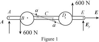
Write the equation of the axial force exerted at the axial point
Here, the force exerted on the frame at the point
Write the equation of the moment of couple formed in the bending moment of the frame and pulley system supported at the point
Here, the axial force exerted on the pulley at point
Write the equation of the axial force exerted at the axial point of the frame from y direction (Refer fig 1).
Here, the axial force exerted on the pulley at point
Sketch the free body diagram for the cable as shown in the Figure 2.
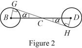
The slope of the cable (Refer fig 2):
The angle formed in the slope of the cable:
Rewrite the above relation to find the angle.
Write the equation of the axial force exerted at the axial point
Here, the angle between the pulley
Sketch the free body diagram for the cable for the point
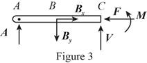
Write the equation of the axial force exerted at the point
Here, shearing force acting on the semicircular rod is
At the pulley
Write the equation of the moment of couple formed in the bending moment supported at the point
Here, the moment of couple exerted at the point
Conclusion:
Substitute
Solve the above equation for
Substitute
Substitute
Substitute
Substitute
The above equation can be written as,
Therefore, the internal forces of shearing force is
(b)
The internal forces exerted at the point
(b)
Answer to Problem 7.15P
The internal forces of shearing force is
Explanation of Solution
Sketch the free body diagram for the cable for the point
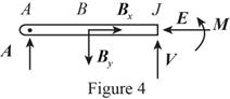
Write the equation of the axial force exerted at the axial point
Here, the force exerted on the frame at the point
Write the equation of the axial force exerted at the axial point of the frame from y direction (Refer fig 4).
Here, the axial force exerted on the pulley at point
Write the equation of the moment of couple formed in the bending moment supported at the point
Here, the moment of couple exerted at the point
Conclusion:
Substitute
Substitute
Substitute
The above equation can be written as,
Therefore, the internal forces of shearing force is
Want to see more full solutions like this?
Chapter 7 Solutions
VECTOR MECHANICS FOR ENGINEERS W/CON >B


- If you have a spring mass damper system, given by m*x_double_dot + c*x_dot + kx = 0 where m, c, k (all positive scalars) are the mass, damper coefficient, and spring coefficient, respectively. x ∈ R represents the displacement of the mass. Using linear stability analysis, show that the system is asymptotically stable. Hint: stability of a linear system z_dot = Az is characterized by the eigenvalues of A.arrow_forwardWhat would the electropneumatic diagram of a circuit with the sequence a+b+c+(a-b-c-) look like?arrow_forward### What would the electropneumatic diagram of a circuit with the sequence a+b+c+(a-b-c-) look like, with a counter, in the fluidsim?arrow_forward
- You are asked to design a unit to condense ammonia. The required condensation rate is 0.09kg/s. Saturated ammonia at 30 o C is passed over a vertical plate (10 cm high and 25 cm wide).The properties of ammonia at the saturation temperature of 30°C are hfg = 1144 ́10^3 J/kg andrv = 9.055 kg/m 3 . Use the properties of liquid ammonia at the film temperature of 20°C (Ts =10 o C):Pr = 1.463 rho_l= 610.2 kf/m^3 liquid viscosity= 1.519*10^-4 kg/ ms kinematic viscosity= 2.489*10^-7 m^2/s Cpl= 4745 J/kg C kl=0.4927 W/m CCalculate the surface temperature required to achieve the desired condensation rate of 0.09 kg/s( should be 688 degrees C) a) Show that if you use a bigger vertical plate (2.5 m-wide and 0.8 m-height), the requiredsurface temperature would be now 20 o C. You may use all the properties given as an initialguess. No need to iterate to correct for Tf. b) What if you still want to use small plates because of the space constrains? One way to getaround this problem is to use small…arrow_forwardA differential element on the bracket is subjected to plane strain that has the following components:, Ɛx = 300 × 10-6, Ɛy = 150 × 10-6, Ɛxy = -750 x 10-6. Use the strain-transformation equations and determine the normal strain Ɛx in the X/ direction on an element oriented at an angle of 0 = 40°. Note, a positive angle, 0, is counter clockwise. x Enter your answer in micro strain to a precision of two decimal places. eg. if your answer is 300.15X10⁶, please enter 300.15.arrow_forwardIf the 50 mm diameter shaft is made from brittle material having an ultimate strength of σult=595 MPa for both tension and compression, determine the factor of safety of the shaft against rupture. The applied force, F, is 140 kN. The applied torque T, is 5.0 kN⚫m. Enter your answer to a precision of two decimal places. T Farrow_forwardЗіс 1 mH 10 Ω m 16 cos 2.5 × 10⁴ A Lic 592 10 Ω 1 μFarrow_forwardHomework#5arrow_forwardHomework#5arrow_forwardOxygen (molar mass 32 kg/kmol) expands reversibly in a cylinder behind a piston at a constant pressure of 3 bar. The volume initially is 0.01 m3 and finally is 0.03 m3; the initial temperature is 17°C. Calculate the work input and the heat supplied during the expansion. Assume oxygen to be an ideal gas and take cp = 0.917 kJ/kg K. For 1 bonus mark explain why (using your understanding of thermodynamics) that oxygen is used in this context rather than water vapour.arrow_forwardarrow_back_iosSEE MORE QUESTIONSarrow_forward_ios
 Elements Of ElectromagneticsMechanical EngineeringISBN:9780190698614Author:Sadiku, Matthew N. O.Publisher:Oxford University Press
 Mechanics of Materials (10th Edition)Mechanical EngineeringISBN:9780134319650Author:Russell C. HibbelerPublisher:PEARSON
 Thermodynamics: An Engineering ApproachMechanical EngineeringISBN:9781259822674Author:Yunus A. Cengel Dr., Michael A. BolesPublisher:McGraw-Hill Education
 Control Systems EngineeringMechanical EngineeringISBN:9781118170519Author:Norman S. NisePublisher:WILEY
 Mechanics of Materials (MindTap Course List)Mechanical EngineeringISBN:9781337093347Author:Barry J. Goodno, James M. GerePublisher:Cengage Learning
 Engineering Mechanics: StaticsMechanical EngineeringISBN:9781118807330Author:James L. Meriam, L. G. Kraige, J. N. BoltonPublisher:WILEY