Videos
(a)
The pump resistance and the steady-state height.
Answer to Problem 7.32P
The pump resistance is
Explanation of Solution
Calculation:
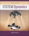
The figure below shows the pump curve and the line for steady-state flow.
Figure-(1)
Write the expression of the two resistances in series.
Here, the outlet flow rate of the tank is
Write the expression of mass conservation.
Here, the outlet flow rate of the tank is
Write the expression of the height of the tank.
Here, the pump resistance is
Refer to Figure-(1) to obtain the pressure rise in the pump as
Substitute
Thus, the pump resistance is
Substitute 0 for
Substitute
Thus, the steady-state height is
(b)
The linearized dynamic model of the height deviation in the tank.
Answer to Problem 7.32P
The linearized dynamic model of the height deviation in the tank is
Explanation of Solution
Calculation:
Write the expression of the linear model.
Write the expression of mass conservation.
Here, the pump resistance is
Write the expression of small deviation in mass flow rates of the mass conservation.
Here, the area of the tank is
Write the expression of the outlet flow rate of the tank.
Write the expression of the deviation.
Here, the area of the tank is
Substitute
Substitute
Substitute
Thus, the linearized dynamic model of the height deviation in the tank is
Want to see more full solutions like this?
Chapter 7 Solutions
EBK SYSTEM DYNAMICS


- Determine the reaction force acting on the beam AB, given F = 680 N. 5 4 4 m 3 3 A B 30° 3 m F (N)arrow_forwardThe frame in the figure is made of an HEA 300 profile (E = 210 GPa, material S355).a) Determine the support reactions at point A. (1p)b) Sketch the bending moment diagram caused by the loading. (1p)c) Using the principle of virtual work (unit load method), calculate the vertical displacement at point B using moment diagrams. Also take into account the compression of the column. (3p)arrow_forward9 kN/m 6 kN/m 3 m 6 m Bestäm, med hjälp av friläggning och jämviktsberäkningar, tvärkrafts- och momentdiagram för balken i figuren. Extrempunkter ska anges med både läge och värde.arrow_forward
- B C 3.0 E F G 40 kN [m] 3.0 3.0 3.0 Fackverket belastas med en punktlast i G enligt figuren. Bestäm normalkraften i stängerna BC, BF och EF.arrow_forwardL q=8 kN/m P= 12 kN En stång belastas av en punklast P vid sin ena ände samt av en jämnt utbredd last q längs hela sin längd. Stången har en tvärsnittsarea A = 150 mm² och är tillverkad av stål med elasticitetsmodul E-210 GPa. Stångens längd, i sitt obelastade tillstånd, är Z-3 m. a) Hur stor är den största normalspänning som uppstår i stången? b) Hur stor blir förlängningen av stången, orsakad av lasterna P och q?arrow_forwardA turbocharged engine with a compression ratio of 8 is being designed using an air standard cycle. The ambient air is assumed to be 300K and 100 kPa. The temperature at the end of the compression in the cylinder is desired to be 1000K, assuming no combustion prior to reaching TDC. At the end of the cylinder expansion the temperature is also desired to be 1000K. If both the turbine and the compressor have mechanical efficiencies of 80%, what will be the pressure ratio of the compressor and what will be the turbine exhaust temperature?arrow_forward
- Q6: A turbocharged engine with a compression ratio of 8 is being designed using an air standard cycle. The ambient air is assumed to be 300K and 100 kPa. The temperature at the end of the compression in the cylinder is desired to be 1000K, assuming no combustion prior to reaching TDC. At the end of the cylinder expansion the temperature is also desired to be 1000K. If both the turbine and the compressor have mechanical efficiencies of 80%, what will be the pressure ratio of the compressor and what will be the turbine exhaust temperature?arrow_forwardQ5: A 5.6 litre V8 engine with a compression ratio of 9.4:1 operates on an air-standard Otto cycle at 2800 RPM, with a volumetric efficiency of 90 % and a stoichiometric air-fuel ratio using gasoline. The exhaust flow undergoes a temperature drop of 44ºC as it passes through the turbine of the supercharger. Calculate (a) mass flow rate of exhaust gas and (b) power available to drive the turbocharger compressor.arrow_forwarddo handwrittenarrow_forward
- Create a report: An example of two people who do not understand each other due to lack of communication, and mention ways to resolve the issue between them .arrow_forwardI want the kinematic diagram to be draw like this plsarrow_forwardAccording to the principles and steps above, draw the kinematic diagram of following mechanisms. Mark the appropriate scale, calculates the degree of freedom. NO.1 NO.2 NO: 3 NO.: 4arrow_forward
 Elements Of ElectromagneticsMechanical EngineeringISBN:9780190698614Author:Sadiku, Matthew N. O.Publisher:Oxford University Press
 Mechanics of Materials (10th Edition)Mechanical EngineeringISBN:9780134319650Author:Russell C. HibbelerPublisher:PEARSON
 Thermodynamics: An Engineering ApproachMechanical EngineeringISBN:9781259822674Author:Yunus A. Cengel Dr., Michael A. BolesPublisher:McGraw-Hill Education
 Control Systems EngineeringMechanical EngineeringISBN:9781118170519Author:Norman S. NisePublisher:WILEY
 Mechanics of Materials (MindTap Course List)Mechanical EngineeringISBN:9781337093347Author:Barry J. Goodno, James M. GerePublisher:Cengage Learning
 Engineering Mechanics: StaticsMechanical EngineeringISBN:9781118807330Author:James L. Meriam, L. G. Kraige, J. N. BoltonPublisher:WILEY