
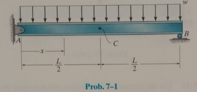
Determine the equation of the elastic curve using the coordinate x, and specify the slope at point A and the deflection at point C. EI is constant.
The equation of elastic curve using the coordinate
Answer to Problem 7.1P
The equation of elastic curve is shown below.
The slope at point A is,
The deflection at C is,
Explanation of Solution
Calculation:
The following figure shows the free body diagram of the beam.
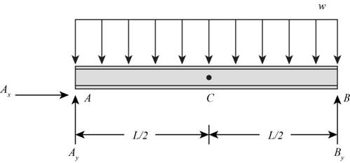
Figure-(1)
Write the Equilibrium Equation for the sum of horizontal forces.
Here, horizontal reaction at A is
Write the Equilibrium Equation for the sum of vertical forces.
Here, vertical reactions at point A and B are
Due to symmetry of the beam, the reactions at point A and B will be half of the total load acting on the beam.
Consider the section x-x at distance
Write the Equation for sum of moment about x-x.
Write the differential equation of the elastic curve as shown below.
Substitute
Here,
Calculate the value of
Apply the boundary conditions at the support points.
At
Substitute
Calculate the value of
At
Substitute
Calculate the slope equation.
Substitute
Calculate the deflection equation.
Substitute
Calculate the slope at A.
Substitute
Calculate the deflection at C.
Substitute
Conclusion:
The equation of elastic curve is shown below.
The slope at point A is,
The deflection at C is,
Want to see more full solutions like this?
Chapter 7 Solutions
EBK STRUCTURAL ANALYSIS
Additional Engineering Textbook Solutions
Starting Out with Programming Logic and Design (5th Edition) (What's New in Computer Science)
Mechanics of Materials (10th Edition)
Electric Circuits. (11th Edition)
Modern Database Management
Java: An Introduction to Problem Solving and Programming (8th Edition)
Computer Science: An Overview (13th Edition) (What's New in Computer Science)

- Can you please explain how to draw the shear and moment diagrams. Thank you.arrow_forwardQ2: Design an activated sludge process to treat a waste flow of 15000 m³/day with a BODs of 180 mg/L following primary treatment. The effluent BOD, and SS are to be 20 m mg/L. Assume Xr = 15000 mg/L, X = 2500 mg/L, 0c = 10 day, Y = 0.60, kd=0.05. Determine 1- the reactor volume, 2- the Sludge production rate, 3- the circulation rate, 4- the hydraulic retention time, and 5- the oxygen required? C₁-Ce C 1 XV = 1 +0.532 QxC₁₂ VXF F= - 1+r (1+0.1r)² = Qr= dt Өс Qx Xr-X V R = [= Q YQ(So-S) Oc dx XV 1+Kd0c O₂demand =1.47 (So-S)Q-[1.14Xr(Qw)] Qw total sludge production/X, S = BOD, effluent - 0.63 * SS Warrow_forwardمارت حولة ملانول 60 Design Deceleration tank and screen for W.W.T.P of flow-144000 m² day Design Data: D.T=1-3 min 1-3b, d=1-1.5 m 60 Design Data: velocity= 0.6: 1.5 m/sec . A-Qdfv=b.d, b=2d 233 Design Data: bars used circular of p= 1.5:3 cm. rec. of (1:2 cm) x (2:6 cm) spacing between bars 2.5:5.0 cm fine screen, 2.5 7.5 cm coarse screen Sloping angle on hz (6)=45:60 = depth of water depth in approaching channel=d = ⚫nbars nspacings +1 ⚫b=nbars xo+nspacings I spacing net inclined area = 2 Aapproach channel=nspacing. spacing. L. 1=d/ sin Check: = 1.13 C 2.56 1134(6.05 P. 45.30 *velocity just befor the screen=v₁ = Qa(m³/sec) screen-b.d ≥ 0.6 m/sec. * velocity through the screen=v2 16mm use 2 Qa(m³/sec) nscreens (spacings Spacing).d ≤1.5 m/sec IsP. 22-65 12²² head losses = Ah = 1.4 x ≤0.1 m 2g bav usp = Ubar Q 23.65 k 148.72arrow_forward
- Q1: Design of trickling filter system single-stage with 3m depth, effluent BOD, of 20 mg/l, influent BODs =250mg/l, flow = 2.63 m³/min and hydraulic flow rate or hydraulic loading rate 25 m/day, r=3arrow_forward04 Q4 A waste effluent of 1.25 m/s with BOD, 183 mg/L, DO=0 mg/L and T = 20 °C is to be discharged into a river of 8 m³/s flow, BOD, = 2mg/L, DO -9.14 mg/L and T= 15 °C. At 20 °C, (K₁) is 0.3/day and (K2) is 0.9/day. The average velocity of the river is 0.8 m/s. 1) Is DO min within the environmental limitations? 2) At what distance is the maximum deficit located. 3) Draw the oxygen sag curve? Given the saturation concentration at 15 °C and at mixed temperature = 10.15 mg/Larrow_forwardCalculate 1- the effluent BOD, of a two-stage trickling filter with the following flows, BOD, and dimensions? Q-5000 m³/day, influent BOD,-280 mg/L, volume of first filter-1000 m³, volume of second filter-800 m³, filter depth-2 m, r₁=1, z=1.25. Also, 2- calculate organic loading rate (BOD, kg/day) 3- Hydraulic loading (m³/m²/d), 4- efficiency of each stage 5- overall removal efficiency.arrow_forward
- Q3: Determine the force in each member of the shown truss, and state whether they are tension or compression. 40 kN 3 m 10 kN A 25-1.25 m m -3.5 m- 3 m Barrow_forwardQ3 Design a secondary clarifier for an activated sludge process with a recycle rate of 25 percent, a MLSS conc. 2500 mg/L, peak flow 9,000 m²/day, depth of tank 3 m and solid loading rate = 4 kg/m²/hrarrow_forwardA- Design grit removal chamber for a W.W.P with hourly flow equal 5000 m'h 410 markarrow_forward
 Principles of Foundation Engineering (MindTap Cou...Civil EngineeringISBN:9781305081550Author:Braja M. DasPublisher:Cengage Learning
 Steel Design (Activate Learning with these NEW ti...Civil EngineeringISBN:9781337094740Author:Segui, William T.Publisher:Cengage Learning
 Residential Construction Academy: House Wiring (M...Civil EngineeringISBN:9781285852225Author:Gregory W FletcherPublisher:Cengage Learning
 Materials Science And Engineering PropertiesCivil EngineeringISBN:9781111988609Author:Charles GilmorePublisher:Cengage Learning
 Engineering Fundamentals: An Introduction to Engi...Civil EngineeringISBN:9781305084766Author:Saeed MoaveniPublisher:Cengage Learning