Concept explainers
Videos
A point at a 6.5-in radius is on a body that is in pure rotation with
- Write an expression for the particle's acceleration vector in position
- Write an expression for the particle's acceleration vector in position
- Write a vector equation for the acceleration difference between points
vectors in this equation and solve for the acceleration difference numerically. - Check the result of part c with a graphical method.
(a)
An expression for the particle’s acceleration vector in position A.
Answer to Problem 7.1P
Acceleration in polar form is
Acceleration in cartesian form is
Explanation of Solution
Calculation:
Compute the angular velocity at point B.
Here,
Substitute
Calculate the angular position at point B.
Here,
Substitute
Compute the magnitude of the normal component of acceleration at point A.
Here,
Compute the direction of the normal component of acceleration at point A.
Compute the magnitude of the tangential component of acceleration at point A.
Here,
Compute the direction of the tangential component of acceleration at point A.
Compute the magnitude of the normal component of acceleration at point B.
Here,
Compute the direction of the normal component of acceleration at point B.
Compute the magnitude of the tangential component of acceleration at point B.
Here,
Compute the direction of the tangential component of acceleration at point A.
Draw the position vector diagram.
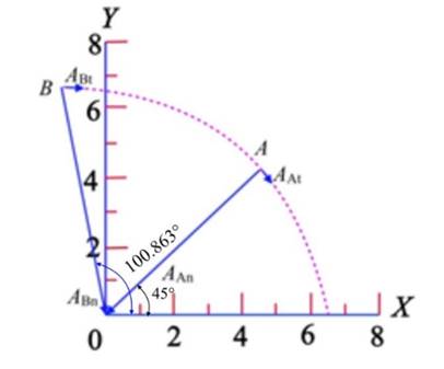
Computer polar form by using the formula.
Calculate the velocity at point A.
Compute the acceleration vector in position A by the following formula.
Compute the acceleration vector of position A in cartesian form.
Therefore, the acceleration of point A is
(b)
An expression for the particle’s acceleration vector in position B.
Answer to Problem 7.1P
Acceleration in polar form is
Acceleration in cartesian form is
Explanation of Solution
Calculation:
Compute the angular velocity at point B.
Here,
Substitute
Calculate the angular position at point B.
Here,
Substitute
Compute the magnitude of the normal component of acceleration at point A.
Here,
Compute the direction of the normal component of acceleration at point A.
Compute the magnitude of the tangential component of acceleration at point A.
Here,
Compute the direction of the tangential component of acceleration at point A.
Compute the magnitude of the normal component of acceleration at point B.
Here,
Compute the direction of the normal component of acceleration at point B.
Compute the magnitude of the tangential component of acceleration at point B.
Here,
Compute the direction of the tangential component of acceleration at point A.
Draw the position vector diagram.

Compute the position vector of point B.
Compute the polar form.
Compute the acceleration vector in position B by the following formula.
Compute the acceleration vector of position B in cartesian form.
(c)
A vector equation for the acceleration difference between points B and A.
Explanation of Solution
Calculation
Calculate the difference in acceleration between the given points.
Therefore, the position difference is
(d)
The answer from the graphical method.
Explanation of Solution
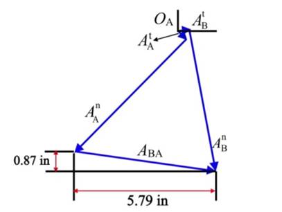
Calculation Solve the equation
Construct the acceleration polygon following the below steps.
- Locate point OA.
- Draw 0.325 in line from the point OA. This represents the velocity of the point
- From the tip of the above line, draw a line of 6.508 in. This represents the acceleration of the point
- From the point OA, draw a 0.325 line which represents the velocity of the point
- From the tip of the point
- From the tip of point
Want to see more full solutions like this?
Chapter 7 Solutions
DESIGN OF MACHINERY-CONNECT ACCESS


- CORRECT AND DETAILED HANDWRITTEN SOLUTION WITH FBD ONLY. I WILL UPVOTE THANK YOU. CORRECT ANSWER IS ALREADY PROVIDED. 1. A H = 6 m cantilever retaining wall is subjected to a soil pressurelinearly varying from zero at the top to 90 kPa at the bottom. As an additionalsupport, it is anchored at depth y = 2 m. with maximum tension equal to 25kN. Assume that the stem provides fully retrained support. Draw the shearand moment diagram of the wall to calculate the following: (a) Maximumpositive bending moment per linear meter; (b) maximum negative bendingmoment per linear meter; (c) maximum shear force per linear meter. answer: +MMax = 440 kn-m, -Mmax = 0kn-M, Vmax = 245 KNarrow_forwardCORRECT AND DETAILED HANDWRITTEN SOLUTION WITH FBD ONLY. I WILL UPVOTE THANK YOU. CORRECT ANSWER IS ALREADY PROVIDED. 17: A simply supported beam with the section shown below has an allowableflexural shearing stress of 43 MPa. (a) Determine the maximum allowable shearing force onthe section. And (b) what is the minimum thickness of plate that should be welded at theflanges if the section is to withstand a total shearing force of 200 kN. The additional plate willhave its base dimension equal to the flange dimension.ANS: V = 179.333 kN ; t = 23.181 mmarrow_forwardCORRECT AND DETAILED HANDWRITTEN SOLUTION WITH FBD ONLY. I WILL UPVOTE THANK YOU. CORRECT ANSWER IS ALREADY PROVIDED. Answer: A = 0.207 L(M)arrow_forward
- Qu 4 The 12-kg slender rod is attached to a spring, which has an unstretched length of 2 m. If the rod is released from rest when 0 = 30°, determine its angular velocity at the instant 0 = 90°. 2 m B k = 40 N/m 2 marrow_forwardCORRECT AND DETAILED HANDWRITTEN SOLUTION WITH FBD ONLY. I WILL UPVOTE THANK YOU. CORRECT ANSWER IS ALREADY PROVIDED. 13: A cantilever beam is of length 1.5 m,loaded by a concentrated load P at its tip as shown inFig. 8-18(a), and is of circular cross section (R = 100 mm),having two symmetrically placed longitudinal holes asindicated. The material is titanium alloy, having anallowable working stress in bending of 600 MPa.Determine the maximum allowable value of the verticalforce P. ANS: P = 236,589.076 N = 236.589 kNarrow_forwardCORRECT AND DETAILED HANDWRITTEN SOLUTION WITH FBD ONLY. I WILL UPVOTE THANK YOU. CORRECT ANSWER IS ALREADY PROVIDED. 15: Consider a beam having an I-type cross section as shown in Fig. 8-45. Ashearing force V of 150 kN acts over the section. Determine the maximum and minimumvalues of the shearing stress in the vertical web of the section.ANS: fv(max) = 44.048 MPa ; fv(min) = 33.202 MPaarrow_forward
- CORRECT AND DETAILED HANDWRITTEN SOLUTION WITH FBD ONLY. I WILL UPVOTE THANK YOU. CORRECT ANSWER IS ALREADY PROVIDED. 12: A steel cantilever beam 16 ft 8 in in length is subjected to a concentrated load of 320 lb acting at the freeend of the bar. A commercially available rolled steel section, designated as W12x32, is used for the beam. Assume that the total depth of the beam is 12 in, and the neutral axis of the section is in the middle. Determine the maximum tensile and compressive stresses. (Properties of commercially available rolled steel section provided in the table. Z = section modulus). ANS: σT = σC = 1,572.482 lb/in2arrow_forwardCORRECT AND DETAILED HANDWRITTEN SOLUTION WITH FBD ONLY. I WILL UPVOTE THANK YOU. CORRECT ANSWER IS ALREADY PROVIDED. 14: Two ½-in x 8-in cover plates are welded to two channels 10 in high to formthe cross section of the beam shown in Fig. 8-59. Loads are in a vertical plane and bendingtakes place about a horizontal axis. The moment of inertia of each channel about ahorizontal axis through the centroid is 78.5 in4. If the maximum allowable elastic bendingstress is 18,000 lb/in2, determine the maximum bending moment that may be developedin the beam.ANS: 1,236,000 lb-in.arrow_forwardCORRECT AND DETAILED HANDWRITTEN SOLUTION WITH FBD ONLY. I WILL UPVOTE THANK YOU. CORRECT ANSWER IS ALREADY PROVIDED. 11: A beam of circular cross section is 7 in in diameter. It is simply supported at each end and loaded by twoconcentrated loads of 20,000 lb each, applied 12 in from the ends of the beam. Determine the maximum bending stressin the beam. ANS: σ = 7,127.172 lb/in2arrow_forward
- using the theorem of three moments, find all the reactions and supportsarrow_forward(An ellipsoidal trapping region for the Lorenz equations) Show that there is a certain ellipsoidal region E of the form rx2 + σy2 + σ(z − 2r)2 ≤ C such that all trajectories of the Lorenz equations eventually enter E and stay in there forever. For a much stiffer challenge, try to obtain the smallest possible value of C with this property.arrow_forwardA) In a factory, an s-type pitot tube was used to calculate the velocity of dry air for a point inside a stack. Calculate the velocity at that point (ft/sec) using following conditions: ● • • Pressure = 30.23 ± 0.01 in Hg (ambient) Pitot tube coefficient = 0.847 ± 0.03 Temperature = 122 ± 0.1 F (stack) Temperature = 71.2 ± 0.1 F (ambient) AP = 0.324 ± 0.008 in H2O (pitot tube) • AP = 0.891 ± 0.002 in H2O (stack) B) Find the dominant error(s) when determining precision for the problem. C) For part A, what is the precision in ft/sec for the velocity?arrow_forward
 Elements Of ElectromagneticsMechanical EngineeringISBN:9780190698614Author:Sadiku, Matthew N. O.Publisher:Oxford University Press
 Mechanics of Materials (10th Edition)Mechanical EngineeringISBN:9780134319650Author:Russell C. HibbelerPublisher:PEARSON
 Thermodynamics: An Engineering ApproachMechanical EngineeringISBN:9781259822674Author:Yunus A. Cengel Dr., Michael A. BolesPublisher:McGraw-Hill Education
 Control Systems EngineeringMechanical EngineeringISBN:9781118170519Author:Norman S. NisePublisher:WILEY
 Mechanics of Materials (MindTap Course List)Mechanical EngineeringISBN:9781337093347Author:Barry J. Goodno, James M. GerePublisher:Cengage Learning
 Engineering Mechanics: StaticsMechanical EngineeringISBN:9781118807330Author:James L. Meriam, L. G. Kraige, J. N. BoltonPublisher:WILEY