
Concept explainers
(a)
Find the quantity of water flowing through the sample per hour.
(a)
Answer to Problem 7.1CTP
The quantity of water flowing through the sample per hour is
Explanation of Solution
Given information:
The length of each soil layer
The total length of the soil layer H is 600 mm.
The diameter of the cylindrical tube d is 150 mm.
The constant head difference
The porosity of the soil layer I
The porosity of the soil layer II
The porosity of the soil layer III
The hydraulic conductivity of soil layer I
The hydraulic conductivity of soil layer II
The hydraulic conductivity of soil layer III
Calculation:
Determine the hydraulic conductivity in the vertical direction using the relation.
Substitute 600 mm for H, 200 mm for
Determine the hydraulic gradient using the relation.
Here, L is the total length of the soil layer.
Substitute 470 mm for
Determine the area of the cylindrical tube using the relation.
Substitute 150 mm for d.
Determine the rate of seepage per unit length of the dam using the relation.
Substitute
Therefore, the quantity of water flowing through the sample per hour is
(b)
Find the elevation head (Z), pressure head
(b)
Answer to Problem 7.1CTP
The elevation head (
The pressure head
The total head
The elevation head (
The pressure head
The total head
The elevation head (
The pressure head
The total head
The elevation head (
The pressure head
The total head
Explanation of Solution
Given information:
The length of each soil layer
The total length of the soil layer H is 600 mm.
The diameter of the cylindrical tube d is 150 mm.
The constant head difference
The porosity of the soil layer I
The porosity of the soil layer II
The porosity of the soil layer III
The hydraulic conductivity of soil layer I
The hydraulic conductivity of soil layer II
The hydraulic conductivity of soil layer III
Calculation:
Determine the elevation head (
Here,
Substitute 220 mm for
Therefore, the elevation head (
Determine the pressure head
Substitute 470 mm for
Therefore, the pressure head
Determine the total head
Substitute 690 mm for
Therefore, the total head
Determine the elevation head (
Substitute 220 mm for
Therefore, the elevation head (
Determine the value of
Substitute
Determine the total head
Substitute 470 mm for
Therefore, the total head
Determine the pressure head
Substitute 436.3 mm for
Therefore, the pressure head
Determine the elevation head
Substitute 220 mm for
Therefore, the elevation head (
Determine the value of
Substitute
Determine the total head
Substitute 436.3 mm for
The total head
Determine the pressure head
Substitute 432.3 mm for
Therefore, The pressure head
Determine the elevation head
Substitute 220 mm for
Therefore, the elevation head (
Determine the value of
Substitute
Determine the total head
Substitute 432.3 mm for
Therefore, the total head
Determine the pressure head
Substitute 432.3 mm for
Therefore, the pressure head
(c)
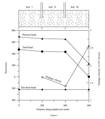
Plot the variation of the elevation head, pressure head, and the total head with the horizontal distance along the sample axis (X–X).
(c)
Explanation of Solution
Given information:
The length of each soil layer
The total length of the soil layer H is 600 mm.
The diameter of the cylindrical tube d is 150 mm.
The constant head difference
The porosity of the soil layer I
The porosity of the soil layer II
The porosity of the soil layer III
The hydraulic conductivity of soil layer I
The hydraulic conductivity of soil layer II
The hydraulic conductivity of soil layer III
Calculation:
Refer Part b)
Draw the graph between the elevation head pressure head, and the total head with the horizontal distance along the sample axis (X–X) as in Figure (1).
(d)
Plot the variation of the discharge velocity and the seepage velocity along the sample axis (X–X).
(d)
Explanation of Solution
Given information:
The length of each soil layer
The total length of the soil layer H is 600 mm.
The diameter of the cylindrical tube d is 150 mm.
The constant head difference
The porosity of the soil layer I
The porosity of the soil layer II
The porosity of the soil layer III
The hydraulic conductivity of soil layer I
The hydraulic conductivity of soil layer II
The hydraulic conductivity of soil layer III
Calculation:
Determine the discharge velocity v using the relation.
Substitute
Determine the seepage velocity of soil I using the relation.
Here,
Substitute 0.000843 cm/sec for v and 0.5 for
Determine the seepage velocity of soil II using the relation.
Here,
Substitute 0.000843 cm/sec for v and 0.6 for
Determine the seepage velocity of soil III using the relation.
Here,
Substitute 0.000843 cm/sec for v and 0.33 for
Draw graph of variation of the discharge velocity and the seepage velocity along the sample axis (X–X).
Refer Figure (1) in Part (c).
(e)
Find the height of the vertical columns of water inside piezometers A and B installed on the sample axis.
(e)
Answer to Problem 7.1CTP
The height of the vertical columns of water at point A is
The height of the vertical columns of water at point B is
Explanation of Solution
Given information:
The length of each soil layer
The total length of the soil layer H is 600 mm.
The diameter of the cylindrical tube d is 150 mm.
The constant head difference
The porosity of the soil layer I
The porosity of the soil layer II
The porosity of the soil layer III
The hydraulic conductivity of soil layer I
The hydraulic conductivity of soil layer II
The hydraulic conductivity of soil layer III
Calculation:
The height of water column is equal to the Piezometric or pressure head at a point.
Determine the height of water in point A.
Substitute 656.3 mm for
Therefore, the height of the vertical columns of water at point A is
Determine the height of water in point B.
Substitute 652.3 mm for
Therefore, the height of the vertical columns of water at point B is
Want to see more full solutions like this?
Chapter 7 Solutions
EBK PRINCIPLES OF GEOTECHNICAL ENGINEER


- STRUCTURAL ANALYSISarrow_forwardA 6m simply supported beam is loaded with a 12 kN-m concentrated moment placed 2m from the left support and a concentrated load of 24 kN located 2m from the right support. The flexural rigidity of the beam is EI. Calculate the slope of the tangent at the left support. Determine the rotation at the right support. Find the deflection at the point of application of concentrated moment. What is the maximum deflection of the beam?arrow_forwardGROUP 1 Design a simply supported prestressed beam to support a parking space with a harped tendon using the ACI 318 Building Code allowable stresses. The span length will be decided by the pair. The pair has to choose a suitable sustained service live load (from 300-1500plf) and superimposed dead load (50-150plf) and has no concrete topping. Assume the beam is made of normal-weight concrete with fc'= 5,000 psi and that the concrete strength f'ci at transfer is 70 percent of the cylinder strength. . Also, the pair must assume a justifiable time-dependent loss. • Assume that that fu = 260,000 psi for stress-relieved tendons, ft = 12sqrt(fc'). THE PAIR MUST BE ABLE TO DEFEND THE LENGTH OF BEAM, AND THE LOADINGS APPLIED ON THE BEAM. DEFEND THE USAGE OF YOUR SELECTED SECTION TYPEarrow_forward
- A trapezoidal drainage ditch along a highway system has a side slope of 2:1 anda bottom width of 8.0 ft. The ditch is to be used to discharge a flow of 500 ft3/sec.If the ditch slope (longitudinal) is 1.0% and the Manning coefficient is 0.02,determine the minimum depth required for the ditch. Is the flow supercritical orsubcritical? Justify your answer.arrow_forwardDetermine the global stiffness matrix of the beam shown in Fig. 3. Assume supports at 1 and 3 are rollers and the support at 2 is a pinned support. Indicate the degrees of freedom in all the stiffness matrices. EI is constant, w=60kN/m, L1=1.25m and L2=3.45marrow_forwardA simply supported beam ten feet long has a 10 Kip load two feet from the left end. What is the maximum moment in the beam? 8 kip-feet 24 kip-feet 16 kip-feet 20 kip-feetarrow_forward
- The moisture content of wood test was performed according to ASTM D4442 procedure and produced the following data:Weight of specimen in the green (moist) condition = 0.70 lbWeight of oven-dry specimen = 0.45.What is the moisture content in percent (%) of the given wood. 64.3 35.7 46.7 55.6arrow_forwardCalculate ALL nodal displacements and ALL the member forces in the truss. Please use the ID's noted in the truss diagramarrow_forwardQ3. In a water flood operation in reservoir A, water is being distributed to severalinjection wells from a common injection system; that is, water is supplied to all thewells at approximately the same well head pressure. Routine measurement of theindividual well injection rates by the team of field operators showed that one well wasreceiving approximately 45% more than its neighbours. The sum of the kh productsfor all of the injection wells were approximately the same depth. As a member of theteam, explain:What are the possible causes of the abnormally high injection rate in this well, andwhat production logs or other tests might be run to further diagnose the problem andplan remedial action?arrow_forward
- Question 1 20 pts Test data on the bending strength of construction wood poles of various diameter are presented below assuming the same length. Kip- 1000 lbf. Using the following data with 2nd order Newton polynomial interpolation, we want to determine the strength of the material for x=4.5 in. Which data point will be used as x? After you found x0, enter the value of x-xo in the solution. Answer shall be in one decimal place. Distance (in) 2.6 1.5 8.3 2.8 5.7 Strength (kips) 100 200 300 400 500arrow_forwardSolve pleasearrow_forwardsolve all of the last names from A-K to please for example use k=100k/in , m =1000lb/g . use el centro (2nd picture ) to solve the questions. Thank you for your help! for the following questions ignore that last name and just solve it pleae: Verify the modes that are orthogonal Normalize the first mode uisng electro with 2%damping, Determine Sa&Sd only for the first modearrow_forward
 Principles of Geotechnical Engineering (MindTap C...Civil EngineeringISBN:9781305970939Author:Braja M. Das, Khaled SobhanPublisher:Cengage Learning
 Fundamentals of Geotechnical Engineering (MindTap...Civil EngineeringISBN:9781305635180Author:Braja M. Das, Nagaratnam SivakuganPublisher:Cengage Learning
 Principles of Foundation Engineering (MindTap Cou...Civil EngineeringISBN:9781337705028Author:Braja M. Das, Nagaratnam SivakuganPublisher:Cengage Learning