Concept explainers
(a)
Find the quantity of water flowing through the sample per hour.
(a)
Answer to Problem 7.1CTP
The quantity of water flowing through the sample per hour is
Explanation of Solution
Given information:
The length of each soil layer
The total length of the soil layer H is 600 mm.
The diameter of the cylindrical tube d is 150 mm.
The constant head difference
The porosity of the soil layer I
The porosity of the soil layer II
The porosity of the soil layer III
The hydraulic conductivity of soil layer I
The hydraulic conductivity of soil layer II
The hydraulic conductivity of soil layer III
Calculation:
Determine the hydraulic conductivity in the vertical direction using the relation.
Substitute 600 mm for H, 200 mm for
Determine the hydraulic gradient using the relation.
Here, L is the total length of the soil layer.
Substitute 470 mm for
Determine the area of the cylindrical tube using the relation.
Substitute 150 mm for d.
Determine the rate of seepage per unit length of the dam using the relation.
Substitute
Therefore, the quantity of water flowing through the sample per hour is
(b)
Find the elevation head (Z), pressure head
(b)
Answer to Problem 7.1CTP
The elevation head (
The pressure head
The total head
The elevation head (
The pressure head
The total head
The elevation head (
The pressure head
The total head
The elevation head (
The pressure head
The total head
Explanation of Solution
Given information:
The length of each soil layer
The total length of the soil layer H is 600 mm.
The diameter of the cylindrical tube d is 150 mm.
The constant head difference
The porosity of the soil layer I
The porosity of the soil layer II
The porosity of the soil layer III
The hydraulic conductivity of soil layer I
The hydraulic conductivity of soil layer II
The hydraulic conductivity of soil layer III
Calculation:
Determine the elevation head (
Here,
Substitute 220 mm for
Therefore, the elevation head (
Determine the pressure head
Substitute 470 mm for
Therefore, the pressure head
Determine the total head
Substitute 690 mm for
Therefore, the total head
Determine the elevation head (
Substitute 220 mm for
Therefore, the elevation head (
Determine the value of
Substitute
Determine the total head
Substitute 470 mm for
Therefore, the total head
Determine the pressure head
Substitute 436.3 mm for
Therefore, the pressure head
Determine the elevation head
Substitute 220 mm for
Therefore, the elevation head (
Determine the value of
Substitute
Determine the total head
Substitute 436.3 mm for
The total head
Determine the pressure head
Substitute 432.3 mm for
Therefore, The pressure head
Determine the elevation head
Substitute 220 mm for
Therefore, the elevation head (
Determine the value of
Substitute
Determine the total head
Substitute 432.3 mm for
Therefore, the total head
Determine the pressure head
Substitute 432.3 mm for
Therefore, the pressure head
(c)
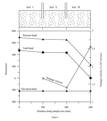
Plot the variation of the elevation head, pressure head, and the total head with the horizontal distance along the sample axis (X–X).
(c)
Explanation of Solution
Given information:
The length of each soil layer
The total length of the soil layer H is 600 mm.
The diameter of the cylindrical tube d is 150 mm.
The constant head difference
The porosity of the soil layer I
The porosity of the soil layer II
The porosity of the soil layer III
The hydraulic conductivity of soil layer I
The hydraulic conductivity of soil layer II
The hydraulic conductivity of soil layer III
Calculation:
Refer Part b)
Draw the graph between the elevation head pressure head, and the total head with the horizontal distance along the sample axis (X–X) as in Figure (1).
(d)
Plot the variation of the discharge velocity and the seepage velocity along the sample axis (X–X).
(d)
Explanation of Solution
Given information:
The length of each soil layer
The total length of the soil layer H is 600 mm.
The diameter of the cylindrical tube d is 150 mm.
The constant head difference
The porosity of the soil layer I
The porosity of the soil layer II
The porosity of the soil layer III
The hydraulic conductivity of soil layer I
The hydraulic conductivity of soil layer II
The hydraulic conductivity of soil layer III
Calculation:
Determine the discharge velocity v using the relation.
Substitute
Determine the seepage velocity of soil I using the relation.
Here,
Substitute 0.000843 cm/sec for v and 0.5 for
Determine the seepage velocity of soil II using the relation.
Here,
Substitute 0.000843 cm/sec for v and 0.6 for
Determine the seepage velocity of soil III using the relation.
Here,
Substitute 0.000843 cm/sec for v and 0.33 for
Draw graph of variation of the discharge velocity and the seepage velocity along the sample axis (X–X).
Refer Figure (1) in Part (c).
(e)
Find the height of the vertical columns of water inside piezometers A and B installed on the sample axis.
(e)
Answer to Problem 7.1CTP
The height of the vertical columns of water at point A is
The height of the vertical columns of water at point B is
Explanation of Solution
Given information:
The length of each soil layer
The total length of the soil layer H is 600 mm.
The diameter of the cylindrical tube d is 150 mm.
The constant head difference
The porosity of the soil layer I
The porosity of the soil layer II
The porosity of the soil layer III
The hydraulic conductivity of soil layer I
The hydraulic conductivity of soil layer II
The hydraulic conductivity of soil layer III
Calculation:
The height of water column is equal to the Piezometric or pressure head at a point.
Determine the height of water in point A.
Substitute 656.3 mm for
Therefore, the height of the vertical columns of water at point A is
Determine the height of water in point B.
Substitute 652.3 mm for
Therefore, the height of the vertical columns of water at point B is
Want to see more full solutions like this?
Chapter 7 Solutions
Principles Of Geotechnical Engineering, Si Edition


- For the beam show below, draw A.F.D, S.F.D, B.M.D A 2 N M 10 kN.m B 2 M Carrow_forwardB: Find the numerical solution for the 2D equation below and calculate the temperature values for each grid point shown in Fig. 2 (show all steps). (Do only one trail using following initial values and show the final matrix) T₂ 0 T3 0 I need a real solution, not artificial intelligence locarrow_forward: +0 العنوان use only Two rods fins) having same dimensions, one made orass (k = 85 Wm K) and the mer of copper (k = 375 W/m K), having of their ends inserted into a furna. At a section 10.5 cm a way from furnace, the temperature of brass rod 120 Find the distance at which the ame temperature would be reached in the per rod ? both ends are ex osed to the same environment. ns 2.05 ۲/۱ ostrararrow_forward
- I need a real solution, not artificial intelligencearrow_forwardI need detailed help solving this exercise from homework of Applied Mechanics. I do not really understand how to do, please do it step by step, not that long but clear. Thank you!arrow_forwardI need detailed help solving this exercise from homework of Applied Mechanics. I do not really understand how to do, please do it step by step, not that long but clear. Thank you!arrow_forward
- I need detailed help solving this exercise from homework of Applied Mechanics. I do not really understand how to do, please do it step by step, not that long but clear. Thank you!arrow_forwardI need detailed help solving this exercise from homework of Applied Mechanics. I do not really understand how to do, please do it step by step, not that long but clear. Thank you!arrow_forwardI need detailed help solving this exercise from homework of Applied Mechanics. I do not really understand how to do, please do it step by step, not that long but clear. Thank you!arrow_forward
- I need detailed help solving this exercise from homework of Applied Mechanics. I do not really understand how to do, please do it step by step, not that long but clear. Thank you!arrow_forwardI need detailed help solving this exercise from homework of Applied Mechanics. I do not really understand how to do, please do it step by step, not that long but clear. Thank you!arrow_forwardI need detailed help solving this exercise from homework of Applied Mechanics. I do not really understand how to do, please do it step by step, not that long but clear. Thank you!arrow_forward
 Principles of Geotechnical Engineering (MindTap C...Civil EngineeringISBN:9781305970939Author:Braja M. Das, Khaled SobhanPublisher:Cengage Learning
 Fundamentals of Geotechnical Engineering (MindTap...Civil EngineeringISBN:9781305635180Author:Braja M. Das, Nagaratnam SivakuganPublisher:Cengage Learning