
a.
Find the current values
a.
Answer to Problem 1P
The current values
Explanation of Solution
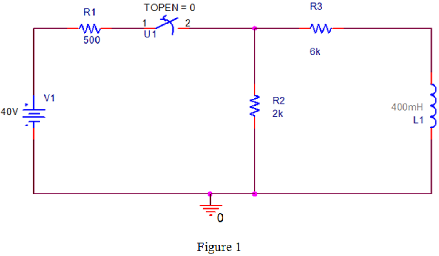
PSPICE Circuit:
Refer to the Figure P7.1 in the textbook.
Draw the given circuit diagram in PSPICE as shown in Figure 1.
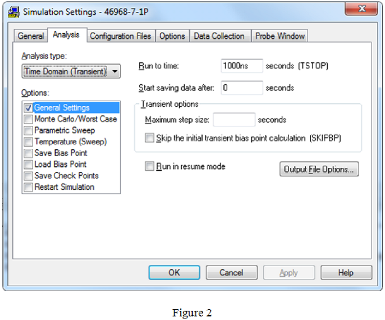
Simulation settings:
Provide the simulation settings as shown in Figure 2.
PSPICE output:
After run the PSPICE circuit a black output screen will be displayed. Right click on the mouse by keeping cursor on the output screen, click the option “Add Trace” and type the expression “-I(R3)” in trace expression box.
The current plot
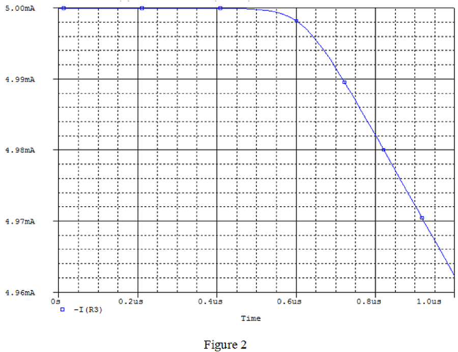
From PSPICE output, the initial values of current are,
Similarly, type the expression “-I(R2)” in trace expression box to obtain the current
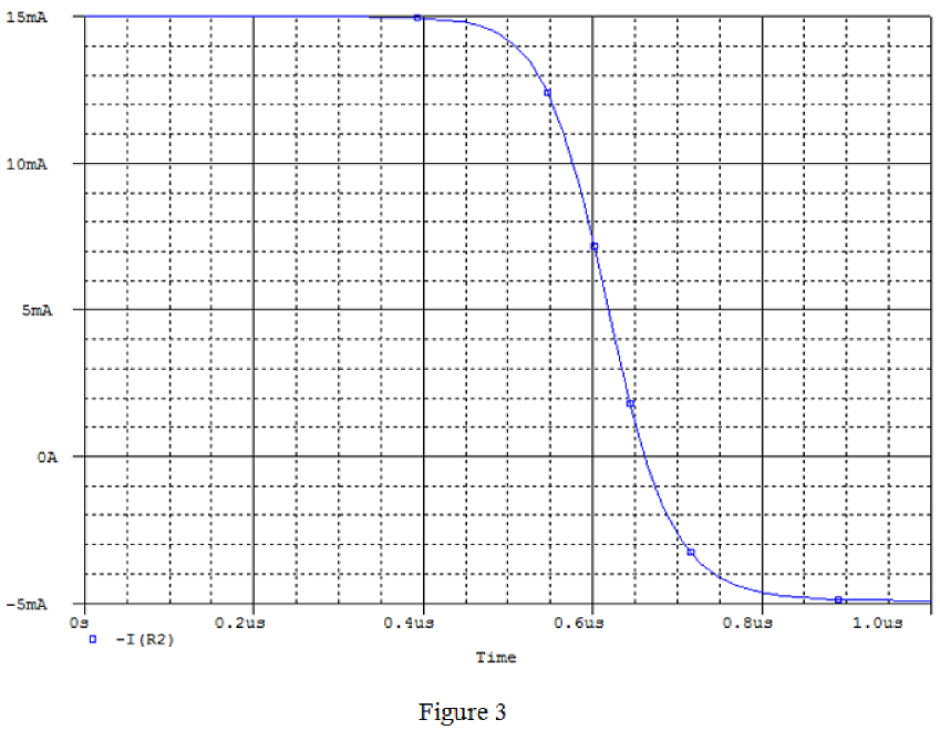
From PSPICE output, the initial values of current are,
Conclusion:
Therefore, the values of
b.
Find the current values
b.
Answer to Problem 1P
The current values
Explanation of Solution
Calculation:
From Figure 2 and Figure 3, the current values are,
Conclusion:
Therefore, the current values
c.
Find the expression
c.
Answer to Problem 1P
The expression
Explanation of Solution
Calculation:
Find the equivalent resistance after the switch is opened at
Find time constant from the circuit diagram.
Here,
L is the inductance.
Substitute
The expression
Substitute 5 mA for
Conclusion:
Therefore, the expression
d.
Find the expression
d.
Answer to Problem 1P
The expression
Explanation of Solution
Calculation:
Find the equivalent resistance after the switch is opened at
Find time constant from the circuit diagram.
Here,
L is the inductance.
Substitute
The expression
Substitute –5 mA for
Conclusion:
Therefore, the expression
e.
Explain the reason for why
e.
Explanation of Solution
Calculation:
The current in the resistor changes instantaneously. The switching operation makes the current
Conclusion:
Therefore, the reason for why
Want to see more full solutions like this?
Chapter 7 Solutions
EBK ELECTRIC CIRCUITS

- Let X and Y be random variables having joint density function 01.5). (c) p(x) and p(y).arrow_forwardThe joint density function of two continuous random variables X and Y is: p(x, y) = {cxy 0 < x < 4,1 < y < 5 0 otherwise Find (i) the constant c (ii)P(1arrow_forwardBelow is a rough schematic of the lighting system for a streetcar powered by a 120 VDC supply. How can I arrange the wires inside the trolley for the interior lights (1-16), headlights (19-20), doors (21-24), and platform lights (17-18), ensuring that each has its own switch? Does the electrical system require additional safety components? What type of cable can be used for wiring these lights?arrow_forward12.8 Obtain the inverse Laplace transform of each of the fol- lowing functions by first applying the partial-fraction-expansion method. (a) Fi(s) 6 = (s+2)(s+4) (b) F2(s) = (c) F3(s) = 4 (s+1)(s+2)2 3s3 +36s2+131s+144 s(s+4)(s²+6s+9) 2s²+4s-10 (d) F4(s) = (s+6)(s+2)²arrow_forward12.4 Determine the Laplace transform of each of the followingfunctions by applying the properties given in the Tables (a) f1(t) = 4te−2t u(t)(b) f2(t) = 10cos(12t +60◦) u(t)*(c) f3(t) = 12e−3(t−4) u(t −4)(d) f4(t) = 30(e−3t +e3t ) u(t)(e) f5(t) = 16e−2t cos4t u(t)(f) f6(t) = 20te−2t sin4t u(t)arrow_forward8. Obtain the inverse Laplace transform of each of the followingfunctions by first applying the partial-fraction-expansionmethod.(a) F1(s) =6(s+2)(s+4)(b) F2(s) =4(s+1)(s+2)2(c) F3(s) =3s3 +36s2 +131s+144s(s+4)(s2 +6s+9)(d) F4(s) =2s2 +4s−10(s+6)(s+2)2arrow_forward12.12 In the circuit of Fig. P12.12(a), is(t) is given by the waveform shown in Fig. P12.12(b). Determine iL (t) for t≥ 0, given that R₁ = R₂ = 2 2 and L = 4 H. is() R₁ R2: (a) Circuit is(t) 8A- 8e-21 elle (b) is(t) Figure P12.12 Circuit and waveform for Problem 12.12. iLarrow_forward12.12 In the circuit of Fig. P12.12(a), is(t) is given by thewaveform shown in Fig. P12.12(b). Determine iL(t) for t ≥ 0,given that R1 = R2 = 2 W and L = 4 H.arrow_forward12.4 Determine the Laplace transform of each of the following functions by applying the properties given in Tables 12-1 and 12-2 on pages 642-643. (a) fi(t)=4tet u(t) (b) f2(t)=10cos (12t+60°) u(t) *(c) f3(t) = 12e−3(t−4) u(t −4) (d) f4(t) = 30(e³ +e³t) u(t) (e) fs(t)=16e2t cos 4t u(t) (f) f6(t)=20te 2 sin 4t u(t)arrow_forwarda) Calculate the values of v and i. + 803 1A Va 82 b) Determine the power dissipated in each resistor. 1A Va (a) + I 50 V 0.2 S (b) + D + 1 Α υ€ 20 Ω 50 V 250 ΩΣ ia (c) (d) Copyright ©2015 Pearson Education, All Rights Reservedarrow_forwardExercise 3-12: Find the Thévenin equivalent of the circuit to the left of terminals (a, b) in Fig. E3.12, and then determine the current I. 502 502 0.6 Ω 20 V | + <302 Ω ΣΙΩ b 2025 Ω 15A Figure E3.12arrow_forward2. Consider following feedback system. r(t) e(t) y(t) K G(s) 1 where G(S) = s²+as+b In above, K, a and b are constants. Select the values of K, a and b in a way so that (i) (ii) (iii) the closed loop system is stable, steady-state error of the closed-loop system for step input is 0.2, the closed-loop response has 20% overshoot and 2 seconds as settling time.arrow_forwardarrow_back_iosSEE MORE QUESTIONSarrow_forward_ios
 Introductory Circuit Analysis (13th Edition)Electrical EngineeringISBN:9780133923605Author:Robert L. BoylestadPublisher:PEARSON
 Delmar's Standard Textbook Of ElectricityElectrical EngineeringISBN:9781337900348Author:Stephen L. HermanPublisher:Cengage Learning
 Programmable Logic ControllersElectrical EngineeringISBN:9780073373843Author:Frank D. PetruzellaPublisher:McGraw-Hill Education
 Fundamentals of Electric CircuitsElectrical EngineeringISBN:9780078028229Author:Charles K Alexander, Matthew SadikuPublisher:McGraw-Hill Education
 Electric Circuits. (11th Edition)Electrical EngineeringISBN:9780134746968Author:James W. Nilsson, Susan RiedelPublisher:PEARSON
 Engineering ElectromagneticsElectrical EngineeringISBN:9780078028151Author:Hayt, William H. (william Hart), Jr, BUCK, John A.Publisher:Mcgraw-hill Education,