
Videos
a)
Find the current values
a)
Answer to Problem 1P
The current values
Explanation of Solution
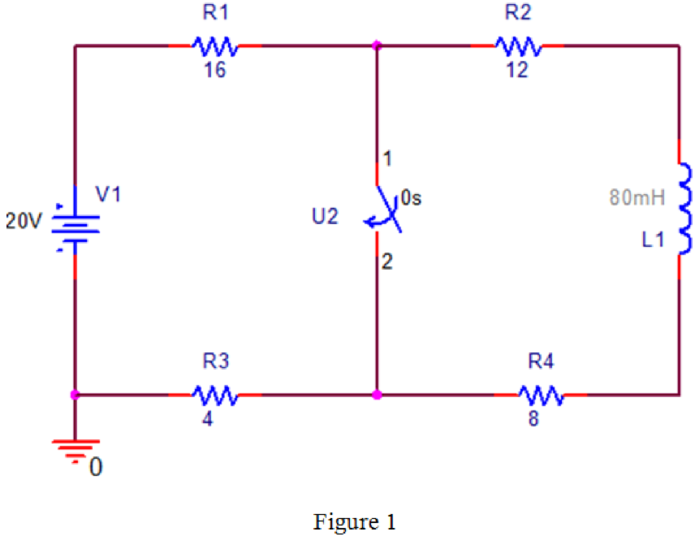
PSPICE Circuit:
Refer to Figure P7.1 in the textbook.
Draw the given circuit diagram in PSPICE as shown in Figure 1.
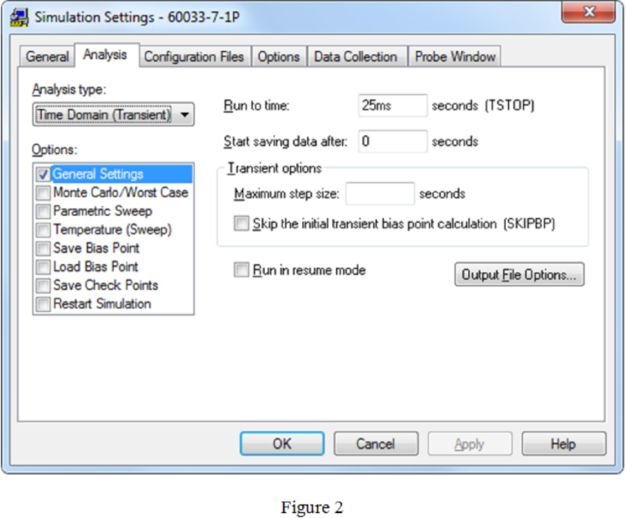
Simulation settings:
Provide the simulation settings as shown in Figure 2.
PSPICE output:
After run the PSPICE circuit a black output screen will be displayed. Right click on the mouse by keeping cursor on the output screen, click the option “Add Trace” and type the expression “I(L1)” in trace expression box.
The current plot
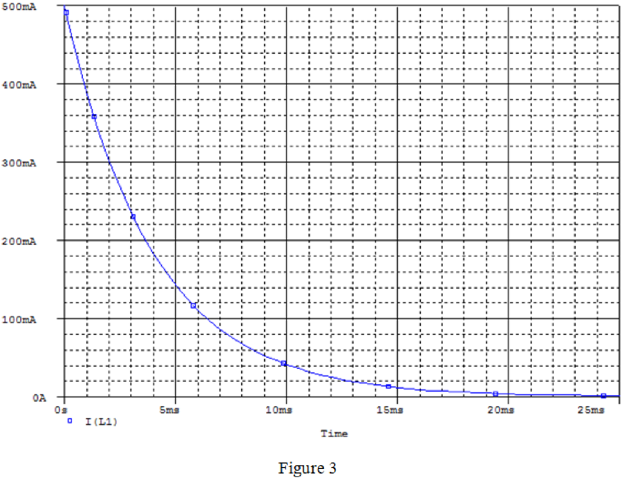
From PSPICE output, the initial and final value of output current is,
Conclusion:
Therefore, the current values
b)
Find the expression
b)
Answer to Problem 1P
The expression
Explanation of Solution
Calculation:
Find the equivalent resistance after the switch is closed at
Find time constant from the circuit diagram.
Here,
L is the inductance.
Substitute
The expression
Substitute
Conclusion:
Therefore, the expression
c)
Find the time taken to reach the output current of 100 mA after closed the switch.
c)
Answer to Problem 1P
The time required to reach 100 mA of output current is 6.4 ms.
Explanation of Solution
Calculation:
The expression of output current
Substitute 100 mA for
Conclusion:
Therefore, the time required to reach 100 mA of output current is 6.4 ms.
Want to see more full solutions like this?
Chapter 7 Solutions
Electrical Circuits and Modified MasteringEngineering - With Access


- Using D flip-flops, design a synchronous counter. The counter counts in the sequence 1,3,5,7, 1,7,5,3,1,3,5,7,.... when its enable input x is equal to 1; otherwise, the counter. This counter is for individual settings only need the state diagram and need the state table to use 16 states from So to S15.arrow_forward: A sequential network has one input (X) and two outputs (Z1 and Z2). An output Z1 Z2 = 10 occurs every time the input sequence 1011 is completed. An output Z1 Z2 = 01 occurs every time the input sequence 0101 is completed. Otherwise Z1 Z2 = 0 Find Moore state diagram with minimum number of states: a) When overlap is allowed. b) When overlap is not allowed. I need a step by step printable solution that uses sequences on the same drawing.arrow_forward1. Consider a negative unity-feedback control system whose plant transfer function is type- 1. Suppose you want to build a lead compensator so that -3 ± 5j are dominant poles. You observed that the angle deficiency at the desired dominant pole is 50°. Compute a 's+b' and b of the lead compensator (s+ 2) so that the error constant Ky is maximized. In other words, design the lead compensator in a way so that the steady-state error for ramp input is minimumarrow_forward
- EXAMPLE 8.12 The E-MOSFET of Fig. 8.40 was analyzed in Example 7.10, with the result that k = 0.24 × 10³ A/V², VGS = 6.4 V, and ID = 2.75 mA. a. Determine gm- b. Find rd. c. Calculate Z; with and without rd. Compare results. d. Find Zo with and without ra. Compare results. e. Find A, with and without rd. Compare results. 카 1 uF Z RE 912 V Rp • 2 ΚΩ 10 ΜΩ HE 1 μF ID (on) = 6 mA VGS (on) = 8 V VGS (Th) = 3 V 80s = 20 μs Za o Voarrow_forwardNO AI PLEASEarrow_forwardNO AI PLEASEarrow_forward
- I need handwritten solution to this, electrical engineering expert tutor s only,this is an assignment,I need 100% accuracyarrow_forward5. Determine the CT convolutions for the signals below. Sketch the signal that flips and on same plot the one that is not flipped. Do this for each overlap case. Clearly indicate all overlap cases and the integral limits. Finally, using the left squiggly bracket notation, show the output for each case versus time. (c) 4 x(t) 2 1 2(t) 4 x(t) 4 0123 et 20 x(t) (4) 4 (a) +(1) 24 T 0123 (b) T (f) 1 2-2 0123 (c) (f) 0123 (d) (1) A t 1(8) 4,121 -101 3 (e)arrow_forwardSolve by pen and paper not using chatgpt or AI Find the current io, and the voltage vo in the circuit in Figure 4. Answer: ἱο = 1.799 Α, νο = 17.99 V.arrow_forward
- "Hi Tutor, Please solve this question manually without using AI tools. AI solutions are often inaccurate in advanced electrical engineering. If you're unable to solve it manually, kindly let another qualified tutor assist me. I need reliable and accurate solutions. Thank you."arrow_forwardQ3: A conducting filamentary triangle joins points A(3, 1, 1), B(5, 4, 2), and C(1, 2, 4). The segment AB carries a current of 0.2 A in the аAB direction. There is present a magnetic field B = 0.2a, -0.1a,+ 0.3a, T. Find: (a) the force on segment BC; (b) the force on the triangular loop; (c) the torque on the loop about an origin at A; (d) the torque on the loop about an origin at C.arrow_forwardI want to find the current by using mesh analysis pleasearrow_forward
 Introductory Circuit Analysis (13th Edition)Electrical EngineeringISBN:9780133923605Author:Robert L. BoylestadPublisher:PEARSON
 Delmar's Standard Textbook Of ElectricityElectrical EngineeringISBN:9781337900348Author:Stephen L. HermanPublisher:Cengage Learning
 Programmable Logic ControllersElectrical EngineeringISBN:9780073373843Author:Frank D. PetruzellaPublisher:McGraw-Hill Education
 Fundamentals of Electric CircuitsElectrical EngineeringISBN:9780078028229Author:Charles K Alexander, Matthew SadikuPublisher:McGraw-Hill Education
 Electric Circuits. (11th Edition)Electrical EngineeringISBN:9780134746968Author:James W. Nilsson, Susan RiedelPublisher:PEARSON
 Engineering ElectromagneticsElectrical EngineeringISBN:9780078028151Author:Hayt, William H. (william Hart), Jr, BUCK, John A.Publisher:Mcgraw-hill Education,