
Videos
Determine the normal force, shear force, and moment at point C.
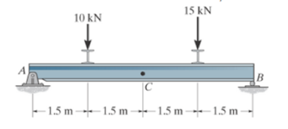
Prob. F7-1
The normal force, shear force, and moment at point C.
Answer to Problem 1FP
The normal force at point C,
The shear force at point C,
The moment at point C,
Explanation of Solution
Assumption:
- Consider the state of the member as tension, where the force is pulling the member, and as compression, where the force is pushing the member.
- The normal force is positive if it creates tension; a positive shear force acting on the segment causes it to rotate clockwise, and a positive bending moment acting on the segment will cause it to bend and concave upwards. Loadings that are opposite to these are considered negative.
- Consider the force indicating the right side as positive and the left side as negative, in the horizontal components of forces.
- Consider the force indicating upside as positive and downside as negative, in the vertical components of forces.
- Consider the clockwise movement as negative and the anti-clockwise movement as positive, wherever applicable.
- The method of sections can be used to determine the internal loadings.
Determine the reactions:
Entire beam:
Show the free body diagram of the entire beam as in Figure (1).
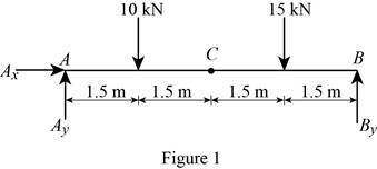
Using Figure (1),
Moment at point A:
Determine the vertical reaction at point B by taking the moment about point A.
Solve Equation (I).
Determine the forces and moment:
Segment CB:
Show the free body diagram of the segment CB as in Figure (2).
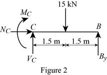
Using Figure (2),
Along the vertical direction:
Determine the shear force at point C by resolving the vertical component of forces.
Along the horizontal direction:
Determine the normal force at point C by resolving the horizontal component of forces.
Moment about point C:
Determine the moment at point C by taking the moment about point C.
Conclusion:
Substitute 13.75 kN for
Thus, the shear force at point C,
Refer to Equation (III).
Thus, the normal force at point C,
Substitute 13.75 kN for
Thus, the moment at point C,
Want to see more full solutions like this?
Chapter 7 Solutions
PEARSON ETEXT ENGINEERING MECH & STATS


- Q5:(? Design the duct system of the figure below by using the balanced pressure method. The velocity in the duct attached to the AHU must not exceed 5m/s. The pressure loss for each diffuser is equal to 10Pa. 100CFM 100CFM 100CFM ☑ ☑ 40m AHU -16m- 8m- -12m- 57m 250CFM 40m -14m- 26m 36m ☑ 250CFMarrow_forwardA mass of ideal gas in a closed piston-cylinder system expands from 427 °C and 16 bar following the process law, pv1.36 = Constant (p times v to the power of 1.36 equals to a constant). For the gas, initial : final pressure ratio is 4:1 and the initial gas volume is 0.14 m³. The specific heat of the gas at constant pressure, Cp = 0.987 kJ/kg-K and the specific gas constant, R = 0.267 kJ/kg.K. Determine the change in total internal energy in the gas during the expansion. Enter your numerical answer in the answer box below in KILO JOULES (not in Joules) but do not enter the units. (There is no expected number of decimal points or significant figures).arrow_forwardmy ID# 016948724. Please solve this problem step by steparrow_forward
- My ID# 016948724 please find the forces for Fx=0: fy=0: fz=0: please help me to solve this problem step by steparrow_forwardMy ID# 016948724 please solve the proble step by step find the forces fx=o: fy=0; fz=0; and find shear moment and the bending moment diagran please draw the diagram for the shear and bending momentarrow_forwardMy ID#016948724. Please help me to find the moment of inertia lx ly are a please show to solve step by stepsarrow_forward
- My ID# 016948724arrow_forwardPlease do not use any AI tools to solve this question. I need a fully manual, step-by-step solution with clear explanations, as if it were done by a human tutor. No AI-generated responses, please.arrow_forwardPlease do not use any AI tools to solve this question. I need a fully manual, step-by-step solution with clear explanations, as if it were done by a human tutor. No AI-generated responses, please.arrow_forward
 International Edition---engineering Mechanics: St...Mechanical EngineeringISBN:9781305501607Author:Andrew Pytel And Jaan KiusalaasPublisher:CENGAGE L
 Mechanics of Materials (MindTap Course List)Mechanical EngineeringISBN:9781337093347Author:Barry J. Goodno, James M. GerePublisher:Cengage Learning